
Seismic source inversion method based on micro seismic data and SPSA optimization algorithm

An optimization algorithm and micro-seismic technology, which is applied in the fields of seismology, seismology, and seismic signal processing for well logging records. It can solve the problem that the positioning accuracy cannot meet the requirements, the speed of algorithm solution is slow, and the initial value selection is highly dependent. and other problems, to achieve fast and accurate source location, reduce interference, and fast calculation speed

Active Publication Date: 2017-05-31
CHINA UNIV OF PETROLEUM (EAST CHINA)
View PDF7 Cites 15 Cited by
  • Summary
  • Abstract
  • Description
  • Claims
  • Application Information

AI Technical Summary

Problems solved by technology

[0004] The core issue of data processing in microseismic monitoring is source location, and the most commonly used inversion method based on travel time, such as longitudinal and transverse wave time difference method or homotype wave time difference method, is a conventional method in microseismic source inversion. However, this method needs to solve linear or nonlinear equations, and there may be overdetermined, underdetermined, or ill-conditioned problems in the process of solving the equations. In addition, this method relies heavily on the event time detected by the geophone, and the positioning accuracy cannot meet the requirements.
[0005] There are also various inversion methods commonly used at present, including some gradient algorithms, such as Newton’s method and conjugate gradient method. The selection dependence is large; there are also some random algorithms, such as particle swarm algorithm, genetic algorithm, simulated annealing method, etc., which can solve the problem of local optimal solution well, but the solution speed of this type of algorithm is slow

Method used


Image

  • Seismic source inversion method based on micro seismic data and SPSA optimization algorithm
  • Seismic source inversion method based on micro seismic data and SPSA optimization algorithm
  • Seismic source inversion method based on micro seismic data and SPSA optimization algorithm

Examples


Embodiment

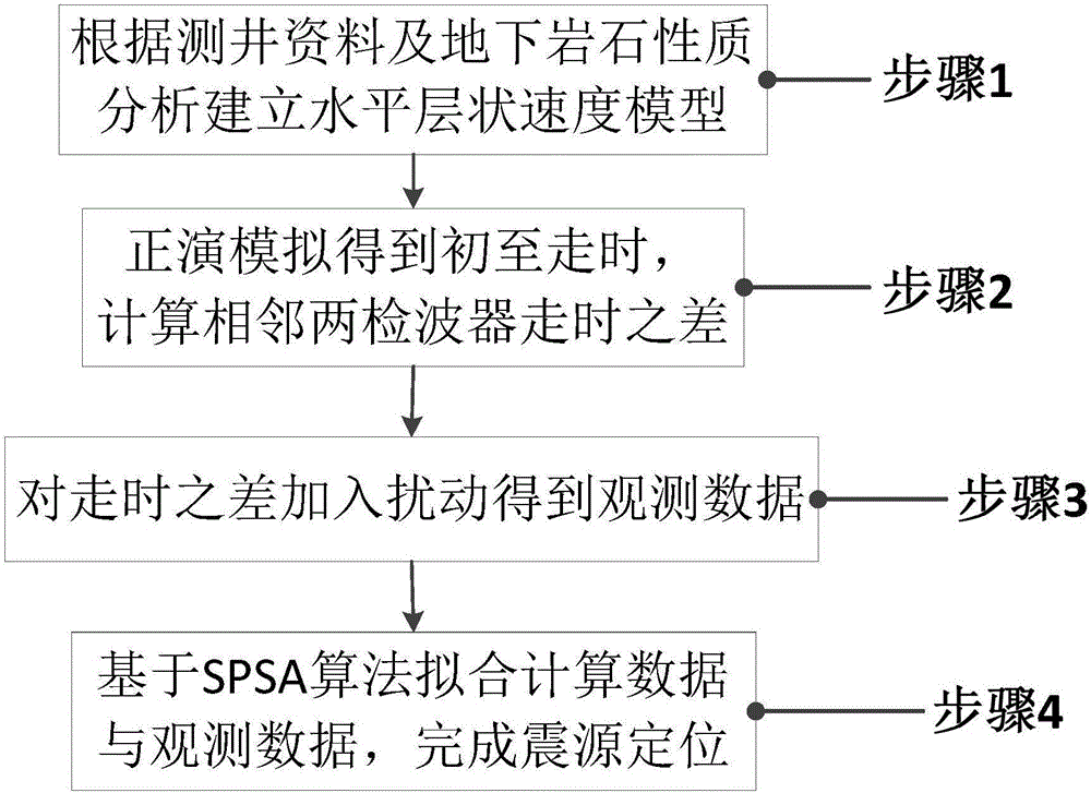
[0096] Based on step 1, a horizontal layered velocity model is established based on well logging data and analysis of underground rock properties: In this calculation example, an area with a length of 400 meters, a width of 400 meters, and a height of 400 meters is selected. They are numbered sequentially from shallow to shallow, and the medium interface is a horizontal plane. The depth of each layer from the ground is Layer_h=[2100 2150 2300 2400]m, and the P wave (longitudinal wave) velocity of the layer interface is Layer_v=[1600 2000 2400] from shallow to deep. 2800] m / s.

[0097] Based on the second step, forward modeling is carried out for a given microseismic event, and the first arrival travel time is calculated, and then the travel time difference between two adjacent geophones is calculated:

[0098] Set the detector parameters as shown in Table 1 below:

[0099] Table 1 Geophone parameters

[0100] series 1 2 3 4 5 6 7 8 9 10 11 12 X 0 ...


PUM


Abstract

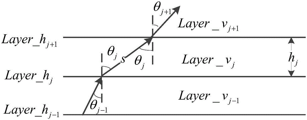
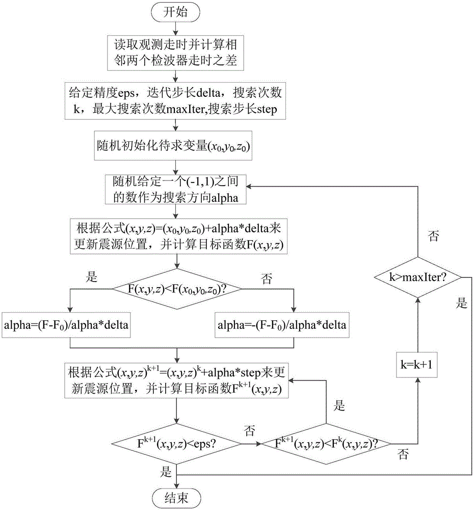
The invention relates to a seismic source inversion method based on micro seismic data and an SPSA optimization algorithm. The method comprises the following steps: building a horizontal layered velocity model according to the analysis of logging data and underground rock property data; fast modeling a micro seismic event, adjusting the angle of ray in a dichotomy approach to optimize the ray tracking path, calculating the first-arrival travel time, and then calculating the travel time difference between two adjacent detectors; adding the travel time difference to random perturbation as an observed value; using an SPSA algorithm to calculate the first-arrival travel time difference in the same way based on the location of a micro seismic source obtained through iterative updating, constantly optimizing the location of the seismic source by fitting calculated data and the observed value, and checking the difference between the calculated data and the observed value; if the precision is satisfied or the maximum number of iterations is achieved, stopping updating, outputting a result, and completing positioning; or, continuing next iteration. By calculating out a micro seismic event source rapidly and efficiently, the accuracy of seismic source locating is improved.

Description

technical field [0001] The invention belongs to the field of oil and gas seismic exploration, and in particular relates to a seismic source inversion method based on microseismic data and an SPSA optimization algorithm. Background technique [0002] In the production process of low-permeability oil and gas fields, fracturing technology is an important measure to increase production and injection, and the fractures generated by fracturing (the fracture orientation is closely related to in-situ stress) and fracturing scale are important factors for well pattern deployment. Therefore, in-depth study of fracture azimuth and shape, and timely adjustment of well patterns have always been urgent issues to be solved in oilfields. [0003] Artificial microseismic real-time monitoring and evaluation technology for fracturing wells is a dynamic monitoring technology for oilfield production based on microseismic monitoring technology. Microseismic monitoring is currently the most accur...

Claims


Application Information

Patent Timeline
Patent Type & Authority Applications(China)
IPC IPC(8): G01V1/28G01V1/40
CPCG01V1/28G01V1/40G01V2210/6169
Inventor 张凯吴海洋张黎明姚军李丽欣张秀清
Owner CHINA UNIV OF PETROLEUM (EAST CHINA)
Learn More