
An infrared variable aperture diaphragm

An aperture diaphragm and infrared fluorescence technology, applied in optics, optical components, instruments, etc., can solve the problem of inability to observe the moving route of the infrared beam spot in real time, and achieve the effect of convenient and efficient adjustment process.

Active Publication Date: 2019-05-28
DALIAN INST OF CHEM PHYSICS CHINESE ACAD OF SCI
View PDF5 Cites 0 Cited by
  • Summary
  • Abstract
  • Description
  • Claims
  • Application Information

AI Technical Summary

Problems solved by technology

[0008] In order to overcome the shortcoming that the ordinary variable aperture diaphragm does not respond to infrared light and cannot observe the moving route of the infrared beam spot in real time, the present invention provides an infrared variable aperture diaphragm that can directly observe the position of the infrared beam spot, so that the infrared beam hits the Visible light can be emitted when the diaphragm is on the diaphragm, and the real-time changes in the direction of the laser beam can be directly observed on the diaphragm when the direction of the laser beam is adjusted

Method used


Image

  • An infrared variable aperture diaphragm
  • An infrared variable aperture diaphragm

Examples


Embodiment Construction

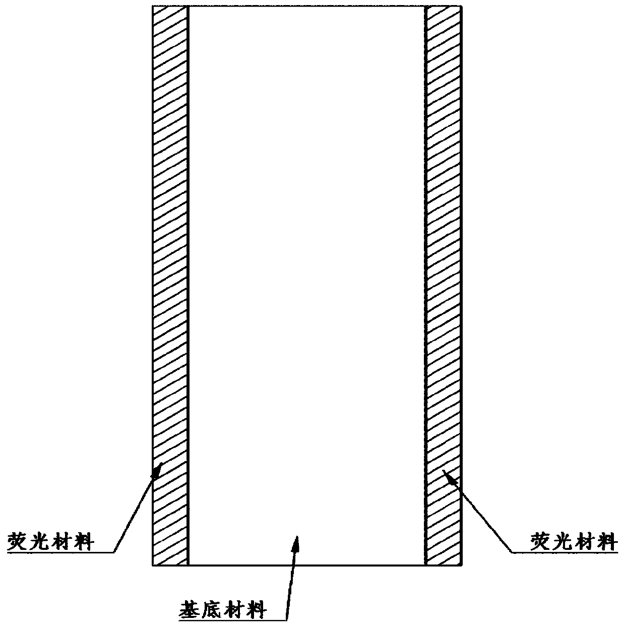
[0021] The present invention provides an infrared variable aperture diaphragm, comprising: a support frame, the support frame is an annular support frame, and a plurality of small circular holes are evenly distributed on it; a rotating disk, and the rotating disk is an annular structure , a plurality of grooves are evenly distributed; a positioning rod, the positioning rod is fixed on the rotating disk, and can drive the rotating disk to rotate; a rotating blade combination, the rotating blade combination is composed of a plurality of rotating blades, the rotating blades The shape is less than 1 / 2 of the circular ring, and there is a fixed pin at both ends, one pin is located, embedded in the round hole of the support frame, and the other pin is located on the other side of the rotating blade, embedded in the groove of the rotating disc Inside, the pin can slide along the groove, and the rotating blade has a structure similar to a sandwich, with an opaque metal sheet in the mid...


PUM


Abstract

The invention relates to an infrared variable aperture diaphragm, which can be used for adjusting the infrared light path. In view of the fact that the infrared beam is invisible to the naked eye, in order to facilitate the adjustment of the infrared light path, an infrared variable aperture diaphragm is constructed by using infrared fluorescent materials and metal opaque materials. The rotating blades of this infrared variable aperture diaphragm have a sandwich-like structure, with an opaque metal sheet in the middle, and the sides are coated with fluorescent materials that emit visible light under infrared light. On the one hand, this infrared variable aperture diaphragm can adjust the aperture size, and on the other hand, it can directly display the position of the infrared beam, which combines the characteristics of the infrared fluorescent display card and the ordinary variable aperture diaphragm. The infrared variable aperture diaphragm has a simple structure and is easy to implement, and can greatly facilitate the adjustment process of the infrared light path.

Description

technical field [0001] The invention relates to the fields of precision optical mechanics and engineering optics, in particular to an infrared variable aperture diaphragm used for infrared light path adjustment. Background technique [0002] When adjusting the optical path, practitioners in the optical field often need to adjust the direction of the laser beam to make it travel along a specific route (generally a straight line is formed by two small holes, so that the laser runs along this straight line). [0003] The rotating blades of the commercially available variable aperture diaphragm are generally made of soft copper material coated with black paint. When the visible beam hits the diaphragm blade, the light spot can be observed with the naked eye, but the infrared beam cannot. Spots of light appear on the aperture. Therefore, for the laser visible to the naked eye, it is very easy to observe its position, and it is relatively easy to adjust. However, for lasers that...

Claims


Application Information

Patent Timeline
Patent Type & Authority Patents(China)
IPC IPC(8): G02B26/04
CPCG02B26/04
Inventor 李留成多丽萍金玉奇于海军王元虎王增强唐书凯李国富汪健曹靖康元福
Owner DALIAN INST OF CHEM PHYSICS CHINESE ACAD OF SCI
Learn More