
Fingerprint identification display device and driving method thereof

A fingerprint recognition and display device technology, applied in static indicators, character and pattern recognition, acquisition/organization of fingerprints/palmprints, etc., can solve the problems of reflected light crosstalk and decrease in fingerprint recognition accuracy, avoiding crosstalk and improving accuracy. Effect

Active Publication Date: 2017-05-31
BOE TECH GRP CO LTD
View PDF7 Cites 89 Cited by
  • Summary
  • Abstract
  • Description
  • Claims
  • Application Information

AI Technical Summary

Problems solved by technology

[0004] However, since the distance between adjacent valleys and ridges of the fingerprint is very small, the reflected light received by the optical sensor is prone to crosstalk, resulting in the problem of decreased fingerprint recognition accuracy after the integration of optical fingerprint detection and display.

Method used


Image

  • Fingerprint identification display device and driving method thereof
  • Fingerprint identification display device and driving method thereof
  • Fingerprint identification display device and driving method thereof

Examples


Embodiment Construction

[0032] The following will clearly and completely describe the technical solutions in the embodiments of the present invention with reference to the accompanying drawings in the embodiments of the present invention. Obviously, the described embodiments are only some, not all, embodiments of the present invention. Based on the embodiments of the present invention, all other embodiments obtained by persons of ordinary skill in the art without making creative efforts belong to the protection scope of the present invention.

[0033] It should be noted that, unless otherwise defined, all terms (including technical and scientific terms) used in the embodiments of the present invention have the same meaning as commonly understood by those of ordinary skill in the art to which the present invention belongs. It should also be understood that terms such as those defined in common dictionaries should be interpreted as having meanings consistent with their meanings in the context of the rel...


PUM

PropertyMeasurementUnit
refractive indexaaaaaaaaaa

Abstract

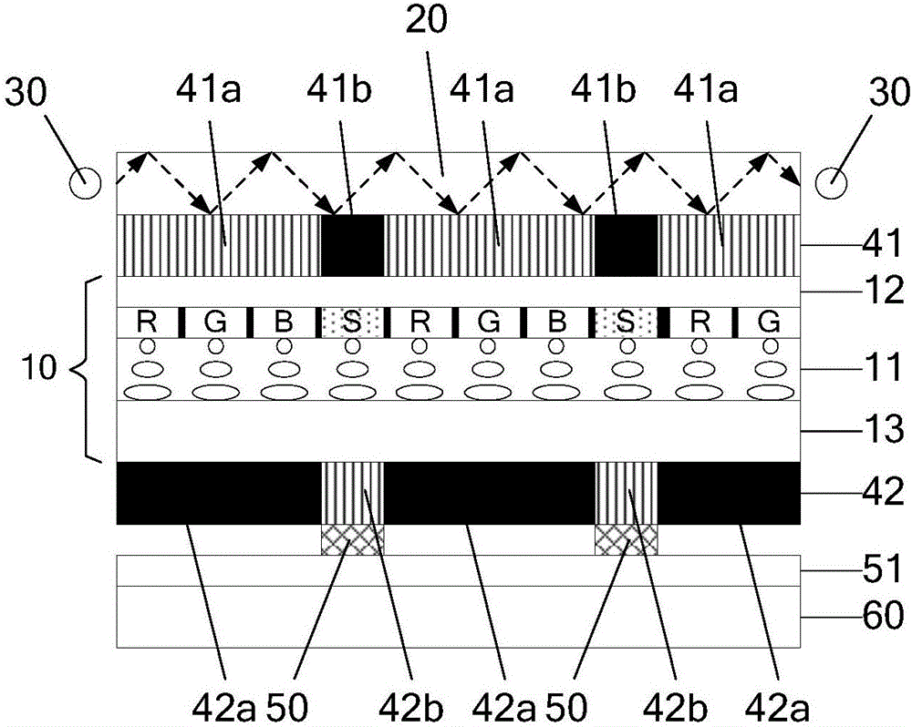
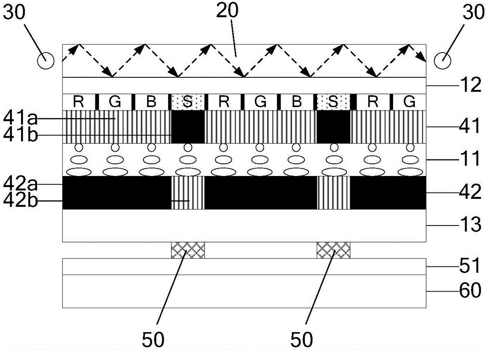
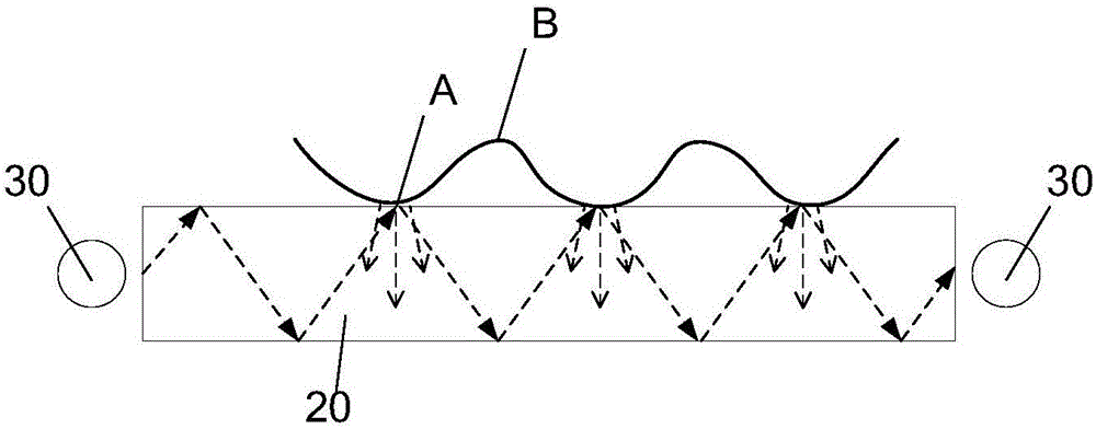
The embodiment of the invention provides a fingerprint identification display device and a driving method thereof, and can improve the precision of fingerprint identification. The device comprises a display panel, a light guide plate, an illumination component, a first polarizer, a second polarizer, and photosensitive induction units. The display panel is encapsulated with a liquid crystal layer and is divided into a plurality of display units; each display unit in a fingerprint identification region comprises a display sub-pixel and an identification sub-pixel. The illumination component is used for making the emitted detecting light to transmit in a total reflection mode in the light guide plate. The first polarizer is arranged between the liquid crystal layer and the light guide plate, and comprises a first region and a second region which are perpendicular in the polarizing direction. The second polarizer is arranged on the other side of the liquid crystal and comprises a third region and a fourth region which are perpendicular in the polarizing direction. The first region and the third region correspond to the display sub-pixel, and have vertical polarizing directions. The photosensitive induction units are arranged on the side of the second polarizer that is away from the liquid crystal layer and each photosensitive induction unit corresponds to each identification sub-pixel.

Description

technical field [0001] The invention relates to the field of display technology, in particular to a fingerprint identification display device and a driving method thereof. Background technique [0002] The principle of optical fingerprint detection is to use the lightness and darkness of the ridges (that is, the protrusions in the ridges) and the valleys (that is, the depressions between the ridges) on the surface of the fingerprint to reflect light differently, and the light and shade of the reflection are reflected by the optical sensor. Optical signals of different degrees are converted into electrical signal output for fingerprint identification. [0003] In existing display devices such as smart phones, the optical sensor is usually arranged in the frame area around the display screen, which results in a low screen-to-body ratio and poor user experience. Therefore, integrating the optical sensor inside the display screen can save the frame area occupied by the optical ...

Claims


Application Information

Patent Timeline
Patent Type & Authority Applications(China)
IPC IPC(8): G02F1/1333G02F1/1335G02F1/1343G09G3/36G06K9/00
CPCG02F1/1333G02F1/133528G02F1/1343G09G3/36G02F1/133548G06V40/1318G02F1/133616G02F1/13338G02F1/133524
Inventor 丁小梁王海生刘英明许睿刘伟王鹏鹏
Owner BOE TECH GRP CO LTD
Learn More