Digital transmission box and fault diagnosing system

A technology of digital transmission and input terminal, applied in the field of digital transmission box and fault diagnosis system, can solve the problems of inability to judge the cause of the fault, low maintenance convenience, etc., to achieve remote reset switching chip control, simple and reliable operation, and improved maintenance convenience. Effect

Active Publication Date: 2017-05-31
广州傲视物联网信息技术有限公司
View PDF13 Cites 1 Cited by
  • Summary
  • Abstract
  • Description
  • Claims
  • Application Information

AI Technical Summary

Problems solved by technology

The traditional digital transmission box only receives and uploads the video data output by the network camera.

Method used


Image

  • Digital transmission box and fault diagnosing system
  • Digital transmission box and fault diagnosing system
  • Digital transmission box and fault diagnosing system

Examples


Example Embodiment

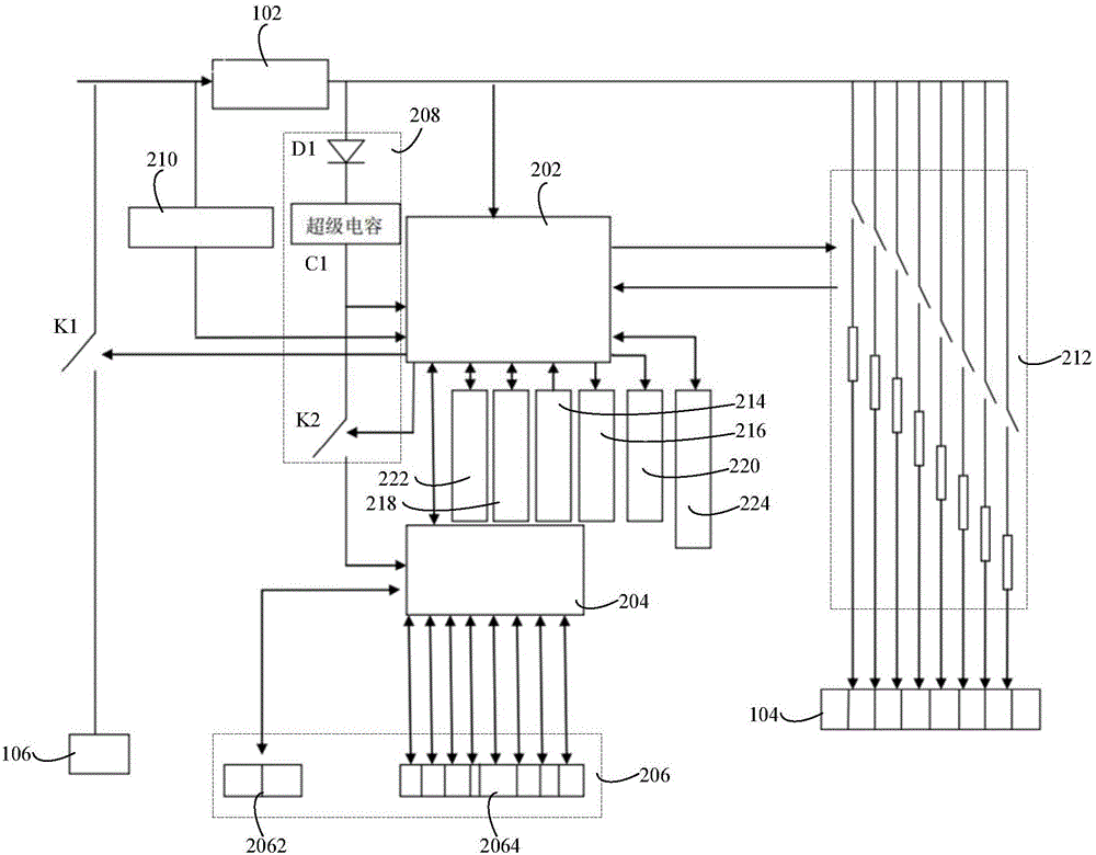
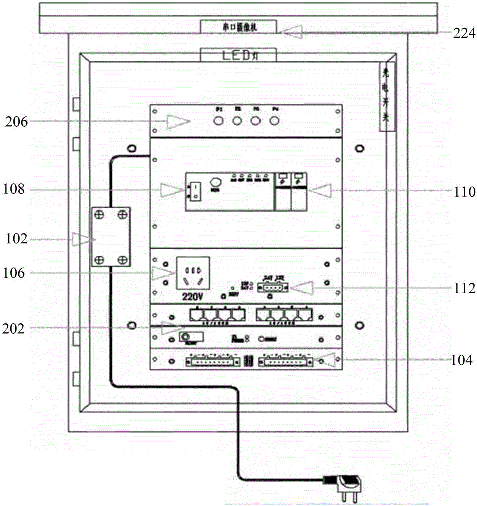
[0015] In one embodiment, a digital transmission box such as figure 1 As shown, it includes a power supply module and a business and main control board. The power supply module includes a switching power supply 102, a controllable DC power output interface 104 and a controllable AC power socket 106. The business and main control board includes a main control single-chip 202 and optical fiber switching. The chip 204, the Ethernet interface 206, the switch chip reset and energy storage circuit 208, the first control switch K1, the mains detection circuit 210, and the output current detection control circuit 212.

[0016] The input end of the switching power supply 102 is used to connect to the mains, the output end of the switching power supply 102 is connected to the output current detection control circuit 212 and the main control microcontroller 202, and the output current detection control circuit 212 is connected to the controllable DC power output interface 104 and the main con...


PUM


Abstract

The invention relates to a digital transmission box and a fault diagnosing system. The digital transmission box comprises a power supply module and a business and master control board card, wherein the power supply module comprises a switching mode power supply, a controllable direct-current power supply output interface and a controllable alternating-current power supply socket; the business and master control board card comprises a master control single chip microcomputer, an optical fiber exchange chip, an Ethernet interface, an exchange chip returning and energy storing circuit, a first control switch, a mains supply detection circuit and an output current detection control circuit master control single chip microcomputer. When direct current output by the switching mode power supply is zero, the mains supply detection circuit is controlled to detect mains supply at the input end of the switching mode power supply, and fault data is generated according to a detection result and sent to the optical fiber exchange chip. After the switching mode power supply powers down and breaks off, a mains supply access situation is detected, the fault data is output from the Ethernet interface through the optical fiber exchange chip, and an operator can accurately judge a fault type of a digital transmission box to timely overhaul the digital transmission box according to the fault type; thus, maintenance convenience is improved.

Description

technical field [0001] The invention relates to the technical field of security monitoring, in particular to a digital transmission box and a fault diagnosis system. Background technique [0002] Entering the 21st century, the global anti-terrorism and security situation is becoming more and more severe, and the role of video surveillance systems is prominent, with tens of thousands of cameras all over every corner of the city. As we all know, due to factors such as lightning strikes, power supply failures, and man-made sabotage, once the optical fiber equipment used as transmission is abnormal, the monitoring of the relevant area is useless. [0003] Abnormalities in the monitoring system may cause very serious consequences, however, such anomalies are often not easy to be discovered by the on-duty personnel. For a large-scale video surveillance system with hundreds or thousands of video points, how to monitor the working status of each front-end equipment in real time and...

Claims


Application Information

Patent Timeline
IPC IPC(8): G05B19/042G05B23/02G08C23/06
CPCG05B19/0428G05B23/0213G05B2219/2604G05B2219/2612G08C23/06
Inventor 于辉周维林
Owner 广州傲视物联网信息技术有限公司
Why Eureka
Try Eureka