Busbar cooling control method and device

A control device and busbar technology, applied in the direction of temperature control, non-electric variable control, control/regulation system, etc., can solve the problems that the response time and accuracy of the temperature sensor cannot be reached, it is difficult to adjust the cooling device, and it cannot be guaranteed. , to achieve the effects of heat dissipation, easy debugging, and good response adjustment

Active Publication Date: 2017-05-31
ZHENGZHOU YUNHAI INFORMATION TECH CO LTD
View PDF10 Cites 2 Cited by
  • Summary
  • Abstract
  • Description
  • Claims
  • Application Information

AI Technical Summary

Problems solved by technology

[0002] The bus bar is a relay station on the main board that is used to collect all data and transmit it. During the operation of the system, the power module and the main control module are usually connected to supply power through the power connector or power cable. Due to the current The power supply current is getting bigger and bigger, and the busbar is more and more widely used, and the heating problem of the busbar when it supplies power over a long distance is becoming more and more prominent. Therefore, the heat dissipation problem of the busbar is becoming more and more urgent. The heat dissipation safety of the busbar must be considered when the power supply is powered at high power, and corresponding control methods must be adopted; in the prior art, the heat dissipation of the busbar is mainly determined by the temperature sensor to detect the temperature, but due to the influence of the medium, the temperature The response time and accuracy of the sensor cannot be reached, and it is difficult to adjust the heat dissipation device in time to achieve the purpose of reducing the temperature, especially when the power supply is powered by high power, the heat dissipation safety of the bus bar cannot be guaranteed.

Method used


Image

  • Busbar cooling control method and device
  • Busbar cooling control method and device
  • Busbar cooling control method and device

Examples


Embodiment 1

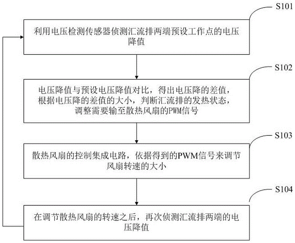
[0032] Such as figure 1 As shown, a method for regulating and controlling the heat dissipation of busbars comprises the following steps:

[0033] Step S101: Use the voltage detection sensor as the detection element in this embodiment, detect the voltage drop value at the preset working point at both ends of the bus bar through the voltage detection sensor, and take the detected voltage drop value as ΔP.

[0034] Step S102: preset voltage drop value: P0, compare the detected voltage drop value ΔP with the preset voltage drop value P0, and obtain the voltage drop difference P, namely: P=P0-ΔP; according to the voltage drop difference The size of the value P determines the heating state of the bus bar, that is, adjusts the PWM signal that needs to be output to the cooling fan, adds the difference P of the voltage drop to the PWM control circuit, and outputs the corresponding PWM signal to the cooling fan by adjusting the duty cycle. Fan control IC.

[0035] Step S103: the contr...

Embodiment 2

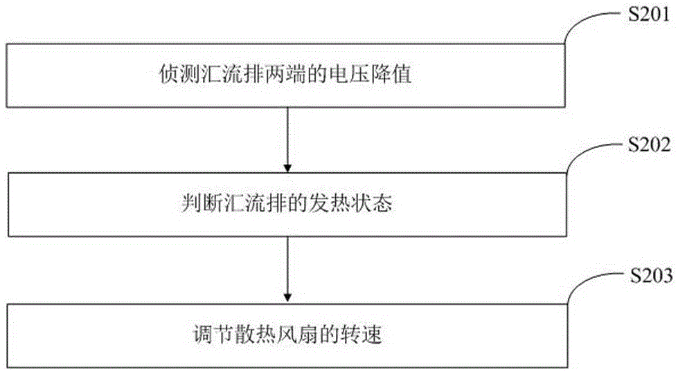
[0038] Such as figure 2 As shown, a method for regulating and controlling the heat dissipation of busbars comprises the following steps:

[0039] Step S201: Detect the voltage drop at both ends of the bus bar;

[0040] Step S202: judging the heating state of the bus bar;

[0041] Step S203: Adjust the rotation speed of the cooling fan.

Embodiment 3

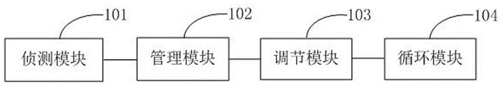
[0043] Such as image 3 As shown, a bus heat regulation device includes: a detection module 301, a management module 302, an adjustment module 303 and a circulation module 304, and the detection module 301 is sequentially connected to the management module 302, the adjustment module 303 and the circulation module 304 .

[0044] The detection module 301 is used to detect the voltage drop at both ends of the bus; the management module 302 is used to judge the heating state of the bus; the adjustment module 303 is used to adjust the speed of the cooling fan; the circulation module is used to adjust the heat dissipation After the speed of the fan is increased, the voltage drop value at both ends of the bus bar is continuously detected.


PUM


Abstract

The invention relates to the technical field of cooling control and discloses a busbar cooling control method. The busbar cooling control method comprises the following steps: detecting voltage drop of two ends of a busbar; judging a thermal state of the busbar; regulating rotating speed of a cooling fan. The invention further provides a busbar cooling control device. The busbar cooling control device comprises a detection module for detecting the voltage drop of two ends of the busbar, a management module for judging the thermal state of the busbar and a regulation module for regulating the rotating speed of the cooling fan. The busbar cooling control method and device have the advantages that the problems that the temperature of the busbar is too high, the cooling state of the busbar cannot be detected precisely in real time and the rotating speed of the cooling fan cannot be regulated when the busbar is powered by a high-power power supply in the prior art are solved, one reliable cooling management method is realized, and the requirement of the system for reliability of the high-power power supply is met.

Description

technical field [0001] The invention relates to the technical field of heat dissipation control, in particular to a method and device for heat dissipation control of busbars. Background technique [0002] The bus bar is a relay station on the main board that is used to collect all data and transmit it. During the operation of the system, the power module and the main control module are usually connected to supply power through the power connector or power cable. Due to the current The power supply current is getting bigger and bigger, and the busbar is more and more widely used, and the heating problem of the busbar when it supplies power over a long distance is becoming more and more prominent. Therefore, the heat dissipation problem of the busbar is becoming more and more urgent. The heat dissipation safety of the busbar must be considered when the power supply is powered at high power, and corresponding control methods must be adopted; in the prior art, the heat dissipati...

Claims


Application Information

Patent Timeline
Patent Type & Authority Applications(China)
IPC IPC(8): G05D23/20
CPCG05D23/20
Inventor 陈宇
Owner ZHENGZHOU YUNHAI INFORMATION TECH CO LTD
Why Eureka
Try Eureka