
Implant structure optimization method based on finite element model

An optimization method and implant technology, applied in gene models, design optimization/simulation, instruments, etc., can solve problems such as inability to adapt to threads, poor bone density, and gingival collapse, and achieve firm fixation and increase implantation time.

Inactive Publication Date: 2021-04-16
DALIAN SANSHENG SCI & TECH DEV
View PDF2 Cites 0 Cited by
  • Summary
  • Abstract
  • Description
  • Claims
  • Application Information

AI Technical Summary

Problems solved by technology

[0003] However, implant objects with older grades or osteoporosis cannot adapt to implants with higher thread density due to their own poor bone density, which is very likely to cause gingival collapse during the implantation process, causing more damage to the patient. big pain

Method used


Image

  • Implant structure optimization method based on finite element model
  • Implant structure optimization method based on finite element model
  • Implant structure optimization method based on finite element model

Examples


Embodiment Construction

[0026] In order to make the purpose, technical solutions and advantages of the embodiments of the present invention more clear, the technical solutions in the embodiments of the present invention are clearly and completely described below in conjunction with the drawings in the embodiments of the present invention:

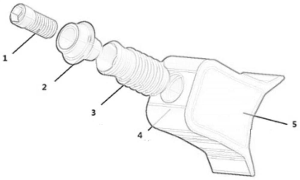
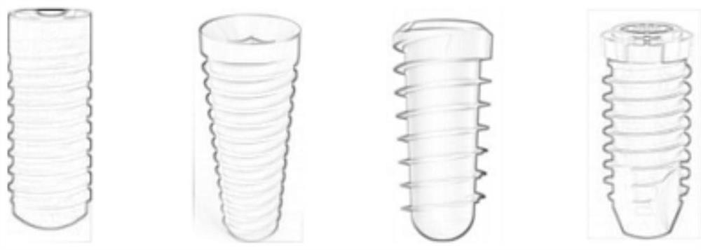
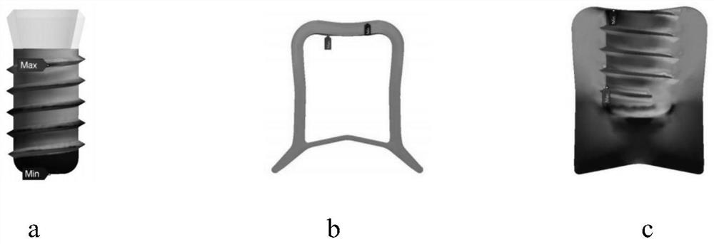
[0027] Such as Figure 1-Figure 4 Shown: An implant structure optimization method based on finite element model, including the following steps:

[0028] - Create a full-scale model of the implant structure to be analyzed, using sample point definitions to create a finite element model.

[0029] — LHD points are evenly distributed in the design space using the Latin hypercube sampling method, maximizing the minimum distance between experimental points;

[0030] —Use LHD as the sampling method and set multiple sampling points to establish the support vector machine regression model SVR; approximate the stress response of the implant-bone interface through the SVR m...


PUM


Abstract

The invention discloses an implant structure optimization method based on a finite element model, comprising the following steps: - establishing a full-scale model of the implant implant structure to be analyzed, and using sample point definitions to create a finite element model; - using a Latin hypercube Sampling method LHD points are evenly distributed in the design space, so that the minimum distance between the experimental points is maximized; - use LHD as the sampling method, and set multiple sampling points, and establish a support vector machine regression model SVR; Line-by-line finite analysis; — approximating the stress response of the implant-bone interface by an SVR model and applying a simulated annealing algorithm to search for optimal results. By establishing the finite element model of the gingival bone and the implant of the terminated object, the SVR model is established by using the LHD design algorithm, and finally the model is verified and optimized. The manufactured implant can be adapted to each implant object. Through 3D printing technology, personalized production can be achieved, which makes the implant more firmly fixed and greatly increases the implantation time.

Description

technical field [0001] The invention relates to an implant structure optimization method based on a finite element model. Involved patent classification number G06 Calculation; Calculation; Counting G06F Electrical digital data processing G06F17 / 00 Digital computing equipment or data processing equipment or data processing methods especially suitable for specific functions G06F17 / 50 Computer-aided design. Background technique [0002] With the coordinated development of dentistry and other disciplines, the structure of implants, especially the thread structure, which was previously neglected, has begun to be paid attention to. The gingiva of implant patients of different ages, genders and physical fitness reflects their own physical fitness, especially It is an intuitive reflection of bone quality. Some young people or people with better bone quality can adapt to implants with higher thread density to obtain more durable implant effects, which can be used for life after impl...

Claims


Application Information

Patent Timeline
Patent Type & Authority Patents(China)
IPC IPC(8): G06F30/23G06F30/27G06N3/12G06F113/10G06F119/14
CPCG06F30/23
Inventor 马跃孙清超蔡俊江张久文彭鹏李闪
Owner DALIAN SANSHENG SCI & TECH DEV
Learn More