

High-voltage DC relay movable reed anti-deflection mechanism
A high-voltage DC, moving reed technology, applied in relays, electromagnetic relays, electromagnetic relay details and other directions, can solve the problem that the return spring cannot be changed by rotating the yoke, the dynamic and static contacts cannot be disconnected in time, and the performance of the relay is affected. and other problems to achieve the effect of avoiding rapid disconnection, reliable and accurate contact, and avoiding failures
- Summary
- Abstract
- Description
- Claims
- Application Information
AI Technical Summary
Problems solved by technology
Method used
Image

Examples
Embodiment 1
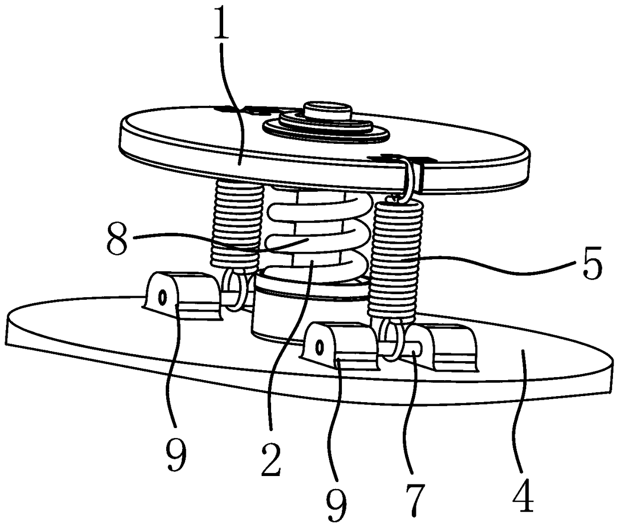
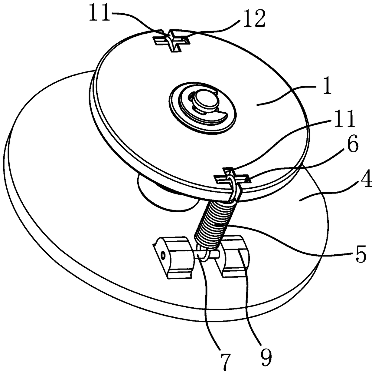
[0024] Depend on figure 1 , figure 2 , image 3 As shown, a high-voltage DC relay moving reed anti-deflection mechanism of the present invention includes a moving contact assembly. The moving contact assembly includes a moving reed 1 and two moving contacts arranged on the moving reed. The moving reed 1 Linked with the push rod 2, the moving reed 1 has a left-right symmetrical structure with the axis of the push rod 2 as the plane of symmetry. Positioning plate 4 is arranged, between the left end of moving reed 1 and positioning plate 4, between the right end of moving reed 1 and positioning plate 4, all be connected with a returning force spring 5. The left and right ends of the moving reed 1 are fixed with an upper slide bar 6, and two slide bars 7 are fixed on the positioning plate 4, and the drag hooks at the upper end of the return force spring 5 are slidably fixed with an upper slide bar 6 respectively, and the return force spring The draw hook of the lower end of 5 ...
Embodiment 2
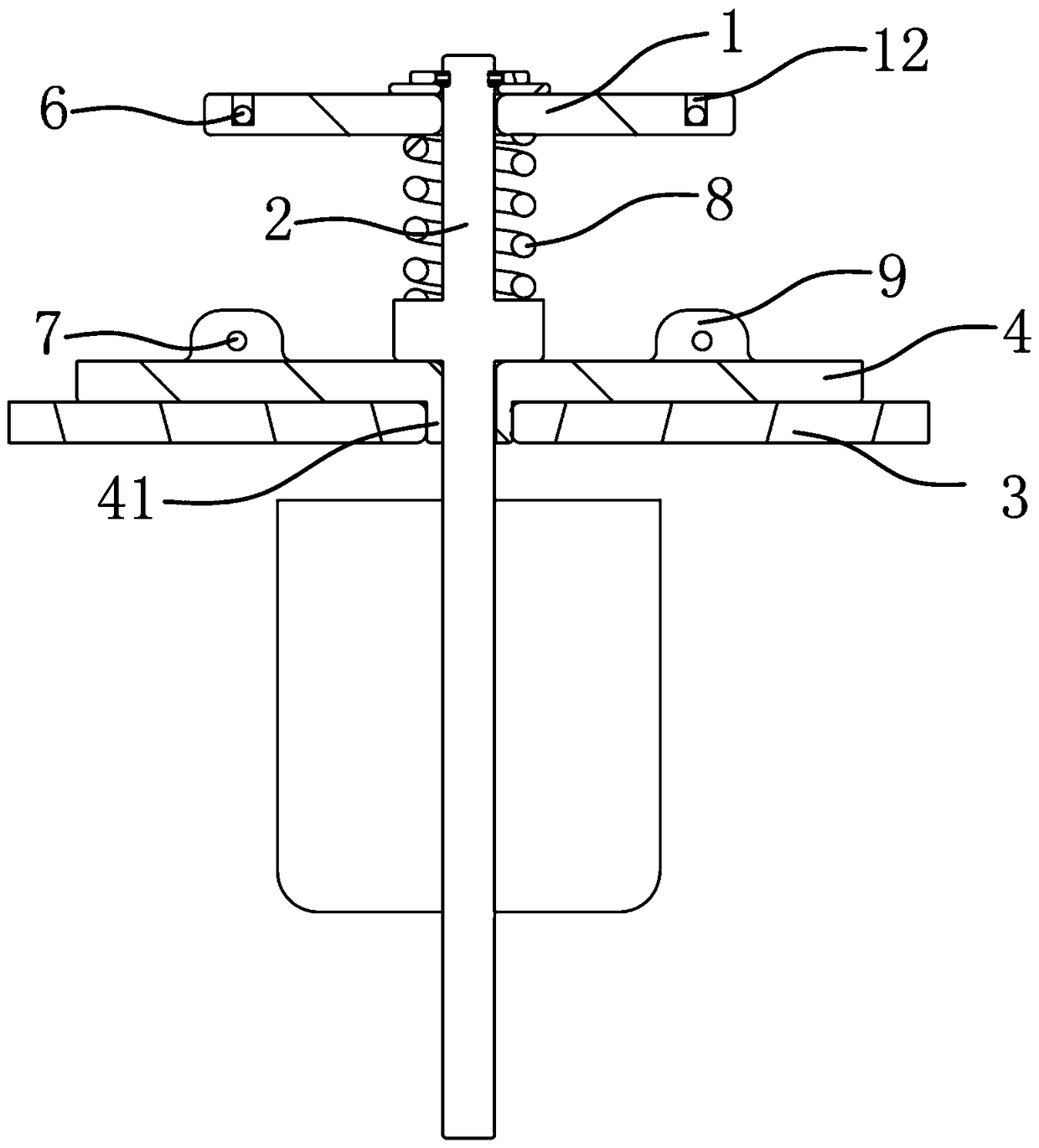
[0030] Depend on Figure 4 As shown, a high-voltage DC relay moving reed anti-deflection mechanism of the present invention includes a moving contact assembly. The moving contact assembly includes a moving reed 1 and two moving contacts arranged on the moving reed. The moving reed 1 Linked with the push rod 2, the moving reed 1 has a left-right symmetrical structure with the axis of the push rod 2 as the plane of symmetry. Positioning plate 4 is arranged, between the left end of moving reed 1 and positioning plate 4, between the right end of moving reed 1 and positioning plate 4, all be connected with a returning force spring 5. The left and right ends of the moving reed 1 are fixed with an upper slide bar 6, and two slide bars 7 are fixed on the positioning plate 4, and the drag hooks at the upper end of the return force spring 5 are respectively fixed with an upper slide bar 6, and the return force spring 5 The drag hooks at the lower end of each are fixed with a slide bar ...
PUM
 Abstract
Description
Claims
Application Information