Eureka AIR delivers breakthrough ideas for toughest innovation challenges, trusted by R&D personnel around the world.

Eccentric particle collecting device with rotated magnetic field

A collection device and particle technology, applied in the direction of magnetic discharge control, etc., can solve the problems of high recirculation rate and low collection efficiency, and achieve the effects of reducing recirculation rate, high collection efficiency and improving particle collection efficiency.

Inactive Publication Date: 2017-05-31
UNIV OF ELECTRONICS SCI & TECH OF CHINA
View PDF5 Cites 0 Cited by
  • Summary
  • Abstract
  • Description
  • Claims
  • Application Information

AI Technical Summary

Problems solved by technology

[0005] The object of the present invention is to overcome the deficiencies of high backflow rate and low collection efficiency of the axisymmetric particle collection device in the prior art, and provide an eccentric particle collection device with magnetic field rotation to reduce the backflow rate and improve particle collection efficiency, thereby Improve the overall efficiency and power of vacuum devices

Method used


Image

  • Eccentric particle collecting device with rotated magnetic field
  • Eccentric particle collecting device with rotated magnetic field
  • Eccentric particle collecting device with rotated magnetic field

Examples


Embodiment Construction

[0017] Specific embodiments of the present invention will be described below in conjunction with the accompanying drawings, so that those skilled in the art can better understand the present invention. It should be noted that in the following description, when detailed descriptions of known functions and designs may dilute the main content of the present invention, these descriptions will be omitted here.

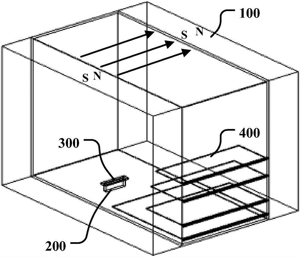
[0018] figure 2 It is a structural schematic diagram of a specific embodiment of the magnetic field rotating eccentric particle collection device of the present invention.

[0019] In this example, if figure 2 As shown, the magnetic field rotating eccentric particle collection device of the present invention includes two magnetic blocks 100 , a particle injection port 200 , and multiple particle collection blades 400 . The two magnetic blocks 100 are rectangular blocks, which are vertically placed in parallel and front and back, and a horizontal magnetic field is formed...


PUM


Abstract

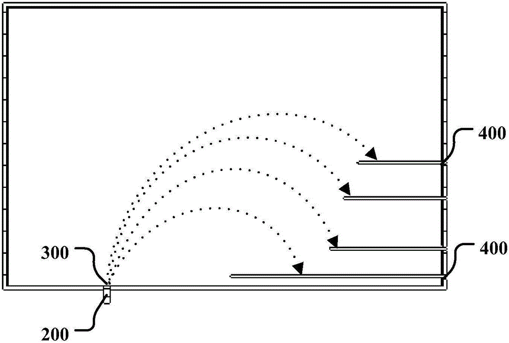
The invention discloses an eccentric particle collecting device with a rotated magnetic field. Two magnets are used for exerting a horizontal magnetic field, so that the particles injected at a lower particle injection end rotate under the effect of the magnetic field, and the rotating plane is vertical to a magnetic field direction; and meanwhile, the particle rotation semi-diameter and the particle energy are in direct proportion; and multiple particle collecting blades close to the particle injection end are orderly arranged at a horizontal direction at one side of the rotating direction from high to low, and the particle collecting blades collect the particles with gradually reduced energies from high to low. The eccentric multi-stage collector blades are used for performing the particle collection, the injected particles rotate under the effect of the magnetic field and deviate from an entry hole of the particle injection end; and meanwhile, if the secondary particles produced through partial collision are in counter rotation reflection from the flank to the entry hole direction, the rotation semi-diameter is greatly reduced due to the magnetic field effect, and majority of secondary particles cannot return to the entry hole position, thereby lowering the reflux rate, and improving the particle collecting efficiency.

Description

technical field [0001] The invention belongs to the technical field of particle collection, and more specifically relates to traveling wave tubes, back wave tubes, klystrons, gyrotrons, free electron lasers, Oro tubes, terahertz maser vacuum electronic devices, and particle linear accelerators Particle collection devices used in vacuum particle devices such as cyclotrons and synchrotron radiation machines Background technique [0002] A particle collection device that must be used in most vacuum devices, including traveling wave tubes, return wave tubes, and linear accelerators. The main function of the particle collection device is to collect the particles that have completed the interaction, that is, to recover the remaining energy, reduce particle radiation and backflow, and enhance heat dissipation. Multistage step-down collectors are often used when the collector and overall device efficiency need to be improved. [0003] Most of the existing particle collection devic...

Claims


Application Information

Patent Timeline
Patent Type & Authority Applications(China)
IPC IPC(8): H01J1/50
CPCH01J1/50
Inventor 刘红伟曹华王战亮崔灿宫玉彬魏彦玉许雄冯进军
Owner UNIV OF ELECTRONICS SCI & TECH OF CHINA
Why Eureka
Eureka Blog
Learn More