Battery component for new energy vehicles

A technology for new energy vehicles and battery components, which is applied to battery pack parts, batteries, electrical components, etc. It can solve the problems of lowering the safety level of automobiles, battery fire extinguishing treatment, and difficult current cut-off, so as to increase the maximum usage, Meet the actual requirements and improve the effect of safety level

Pending Publication Date: 2017-05-31
苏州索尔智行新能源科技有限公司
View PDF9 Cites 7 Cited by
  • Summary
  • Abstract
  • Description
  • Claims
  • Application Information

AI Technical Summary

Problems solved by technology

[0006] 1) Since the battery cell is a three-dimensional shape, the fire extinguishing bag cannot fully extinguish the fire of the battery cell, so it may prolong the time for extinguishing the fire source and reduce the safety level of the car
[0007] 2) The capacity of the fire extinguishing bag is limited, and the effect of fire extinguishing cannot be guaranteed
[0008] 3) The distribution of batteries is unreasonable, which directly leads to the excessive volume of the battery, which cannot meet the actual needs
[0009] 4) After the battery temperature is too high, the control circuit board is easily damaged, and the probability of the core catching fire and exploding is also multiplied
[0010] 5) Once the battery cell burns or explodes, the current is not easy to be cut off, and it is easy to cause a bigger fire

Method used


Image

  • Battery component for new energy vehicles
  • Battery component for new energy vehicles
  • Battery component for new energy vehicles

Examples


Embodiment Construction

[0047] Preferred embodiments of the present invention will be described in detail below in conjunction with the accompanying drawings.

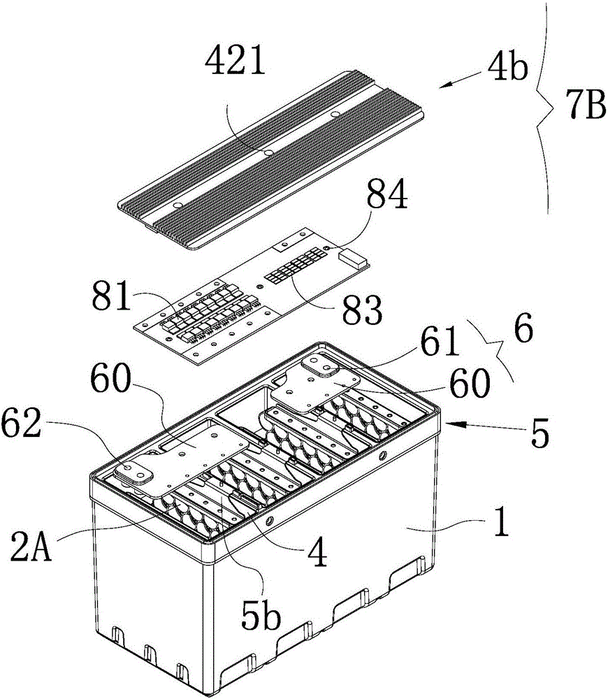
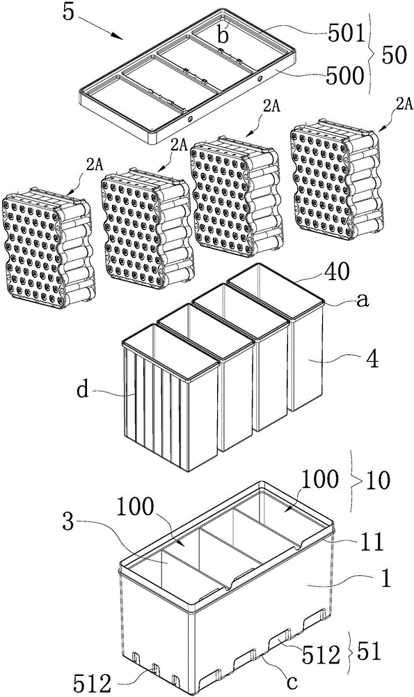
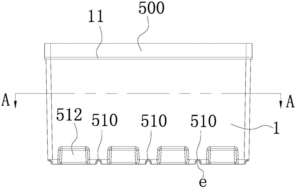
[0048] like Figure 1 to Figure 10 As shown, the battery assembly for new energy vehicles involved in this embodiment includes a housing 1, a plurality of battery cells 2A placed in the housing 1, and a cavity 10 arranged in the housing 1 to separate the cavity 10 into a plurality of The separator 3 of the sub-cavity 100, the liner 4 located in each sub-cavity, the positioning member 5 for positioning and connecting the multiple liners 4 with the housing 1, the battery cover 6, the heat dissipation assembly 7B, and the control circuit Board 8, in which a plurality of sub-cavities 100 are arranged in rows horizontally and vertically or distributed in rows longitudinally, wherein the battery cells 2A are correspondingly arranged in the inner tank 4, the inside of the separator 3 has accommodating spaces connected to each other, and the battery ...


PUM

PropertyMeasurementUnit
melting pointaaaaaaaaaa

Abstract

The invention relates to a battery component for new energy vehicles. The battery component comprises a shell, a plurality of cells placed in the shell, division elements arranged in the shell for dividing the hollow cavity into a plurality of sub-cavities, a battery upper cover, a heat dissipation component and a control circuit board, wherein the plurality of sub-cavities are horizontally arranged in rows, longitudinally arranged in columns or longitudinally arranged in rows; the battery component further comprises a liner located in each sub-cavity; the electric cores are correspondingly arranged in the liners; accommodation spaces communicating with one another are formed in the division elements; the battery component further comprises a fire extinguishing agent fills the accommodation spaces; the heat dissipation component comprises cooling fins and heat conduction elements; and the control circuit board separates the upper surfaces of the heat conduction elements from the lower surfaces of the cooling fins. The battery component provided by the invention can comprehensively protect each electric core and increase the maximum usage amount of the fire extinguishing agent, and meanwhile, the electric cores are reasonably distributed to reduce the volume of the battery component. In addition, the electric cores and the control circuit board can be cooled in time, thereby greatly improving the safety level of the vehicles.

Description

technical field [0001] The invention belongs to the technical field of new energy batteries, and in particular relates to a battery assembly for new energy vehicles. Background technique [0002] As we all know, after generating electricity from petroleum and using batteries to store energy to drive cars, the energy consumed is about 1 / 4 of that directly used by fuel. At the same time, with the rise of the concept of environmental protection, various new energy vehicles are currently developing more actively. [0003] Currently commonly used vehicle batteries, in order to pursue higher energy density, most manufacturers use lithium batteries. However, the biggest disadvantage of lithium batteries is instability and high heat generation. When lithium batteries are deformed by external impacts, they tend to accumulate high temperatures, and even catch fire and explode. [0004] In response to the above-mentioned technical problems, some batteries with self-fire extinguishing...

Claims


Application Information

Patent Timeline
Patent Type & Authority Applications(China)
IPC IPC(8): H01M2/10H01M10/613H01M10/625H01M10/655H01M10/6551A62C3/07A62C3/16
CPCA62C3/07A62C3/16H01M10/613H01M10/625H01M10/655H01M10/6551H01M2220/20H01M50/20Y02E60/10
Inventor 季伟源王乾钱科
Owner 苏州索尔智行新能源科技有限公司
Why Eureka
Try Eureka