
Large-current connection plug bush

A high-current, plug-in technology, applied in the direction of connection, parts and circuits of connecting devices, can solve the problems of easy blackening, easy detachment, and difficulty in bearing the impact of large current at the contact point, so as to strengthen the floating support and The effect of connecting, ensuring the insertion angle, and increasing the contact area

Inactive Publication Date: 2017-05-31
CHANGZHOU NUODE ELECTRONICS
View PDF9 Cites 0 Cited by
  • Summary
  • Abstract
  • Description
  • Claims
  • Application Information

AI Technical Summary

Problems solved by technology

[0002] At present, the contacts of the existing electric connectors for new energy vehicles include split sockets, crown spring socket assemblies and wire spring socket assemblies, but there are the following deficiencies in use: (1) socket method The contact resistance is large, the tensile strength is poor, and it is easy to detach after contact, causing connection failures and accidents; (2) The structure is complex, there are many combined parts, and the volume cannot be further reduced, which is not conducive to the development of miniaturization and densification; (3) Processing technology Complexity, high precision requirements, resulting in low product qualification rate and high cost; (4) It is difficult to withstand the impact of large current, and does not support live plugging and unplugging
In order to reduce the contact resistance, cage-type or hyperboloid sockets are mostly used now. In use, the insertion of the pins cannot guarantee a certain angle, and the pins are mostly inclined when inserted, resulting in partial contact between the pin and the reed. Contact, instantaneous large current, sparks, easy to blacken at the contact point, severely damage the reed, and reduce the conductivity after repeated plugging and unplugging, and the cage or hyperboloid socket cannot be used for live operation. The effective contact area is still small and the conductivity is unstable

Method used


Image

  • Large-current connection plug bush
  • Large-current connection plug bush
  • Large-current connection plug bush

Examples


Embodiment 1

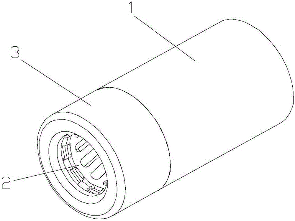
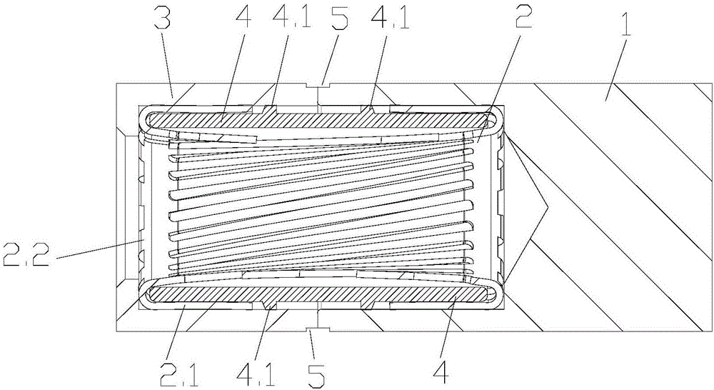
[0027] Embodiment 1: refer to Figure 1 to Figure 3 , high-current connection socket, including bushing 1, reed 2 inside bushing 1, the front end of bushing 1 is provided with conductive front end cover 3, the materials of front end cover 3 and bushing 1 are brass, and the front end cover The outer diameter of 3 is consistent with the outer diameter of casing 1, and the front end cover 3 is fixedly connected with casing 1, and eight quadrilateral pit-shaped closing structures 5 are stamped at the joint through closing equipment, and the closing structure 5 can strengthen the front end cover 3 more than The connection between the sleeves 1 prevents loosening between the front cover 3 and the sleeves after long-term plugging and unplugging. The front cover 3 and the sleeve 1 form a hollow cavity. The front end of the front cover 3 is provided with an opening. There is a 45° chamfer structure, the reed 2 is set in the hollow cavity, the outer sleeve of the reed 2 is provided with...

Embodiment 2

[0029] Embodiment 2: refer to Figure 1 to Figure 3, high-current connection socket, including bushing 1, reed 2 inside bushing 1, the front end of bushing 1 is provided with conductive front end cover 3, the materials of front end cover 3 and bushing 1 are brass, and the front end cover The outer diameter of 3 is consistent with the outer diameter of casing 1, and the front end cover 3 is fixedly connected with casing 1, and the joint is stamped with four line-segment-shaped concave closing structures 5 through closing equipment, and the closing structure 5 can strengthen the front cover 3 and other casings 1 connection to avoid loosening between the front cover 3 and the casing after long-term plugging and use. The front cover 3 and the casing 1 form a hollow cavity. The front end of the front cover 3 is provided with an opening. ° chamfering structure, the reed 2 is set in the hollow cavity, the reed 2 is provided with an inner bushing 4, and the inner bushing 4 is provided...

Embodiment 3

[0031] Embodiment 3: refer to Figure 1 to Figure 3 , high-current connection socket, including bushing 1, reed 2 inside bushing 1, the front end of bushing 1 is provided with conductive front end cover 3, the materials of front end cover 3 and bushing 1 are brass, and the front end cover The outer diameter of 3 is consistent with the outer diameter of casing 1, and the front end cover 3 is fixedly connected with casing 1, and eight rectangular pit-shaped closing structures 5 are stamped at the joint through closing equipment, and the closing structure 5 can strengthen the front end cover 3 more than The connection between the sleeves 1 prevents loosening between the front cover 3 and the sleeves after long-term plugging and unplugging. The front cover 3 and the sleeve 1 form a hollow cavity. The front end of the front cover 3 is provided with an opening. There is a 45° chamfer structure, the reed 2 is set in the hollow cavity, the outer sleeve of the reed 2 is provided with a...


PUM


Abstract

The invention belongs to the technical field of a connector and specifically relates to a large-current connection plug bush. The large-current connection plug bush comprises a sleeve pipe and reeds in the sleeve pipe. The front end of the sleeve pipe is provided with a conductive front end cover; the front end cover is fixedly connected with the sleeve pipe; the front end cover and the sleeve pipe form a hollow cavity; the reeds are arranged in the hollow cavity; the front end of the front end cover is an opening; the reeds are externally sleeved by an inner bush; the body of the inner bush is provided with circumference bosses; the circumference bosses are distributed at the two sides of each joint place of the sleeve pipe and the front end cover; the outer wall surface of each circumference boss is contacted with the sleeve pipe or the front end cover inner wall surface; each joint place of the sleeve pipe the front end cover is provided with a closing-in structure; the peripheral surface of each reed is an internally-concave surface, which is big at the two ends and small in the middle; and the inner diameter at the middle portion of the reed is minimum, and inner diameter difference between the minimum internal diameter and the internal diameter of the end surface of the reed is 0.35-0.7 mm. The large-current connection plug bush is high in conductivity, can operate alive, can realize smooth contact pin insertion and conduction in advance and prevents black coating due to generation of sparks.

Description

technical field [0001] The invention belongs to the technical field of connectors, and in particular relates to a high-current connection socket. Background technique [0002] At present, the contacts of the existing electric connectors for new energy vehicles include split sockets, crown spring socket assemblies and wire spring socket assemblies, but there are the following deficiencies in use: (1) socket method The contact resistance is large, the tensile strength is poor, and it is easy to detach after contact, causing connection failures and accidents; (2) The structure is complex, there are many combined parts, and the volume cannot be further reduced, which is not conducive to the development of miniaturization and densification; (3) Processing technology Complexity and high precision requirements lead to low product qualification rate and high cost; (4) It is difficult to withstand the impact of large current and does not support live plugging. In order to reduce the...

Claims


Application Information

Patent Timeline
Patent Type & Authority Applications(China)
IPC IPC(8): H01R13/187H01R13/631
CPCH01R13/187H01R13/631
Inventor 戴仁益王利甫王培记
Owner CHANGZHOU NUODE ELECTRONICS
Learn More