A cable head manufacturing device using electric control grating linkage

A technology for manufacturing devices and cable heads, which is applied in the direction of equipment for connecting/terminating cables, etc. It can solve problems such as increased working current, interrupted production, scientific research, medical operations, fires, etc., and achieves the effect of a good conductor

Active Publication Date: 2018-05-11
安徽爱谱华顿电子科技有限公司
View PDF10 Cites 0 Cited by
  • Summary
  • Abstract
  • Description
  • Claims
  • Application Information

AI Technical Summary

Problems solved by technology

The heating of wire joints will not only cause a large amount of power loss, but also seriously affect the normal operation of electrical equipment. At least, the working current in the line will increase, and the life of electrical equipment will be shortened. Surgery and other activities will also cause fire and electric shock accidents, etc., causing incalculable losses

Method used


Image

  • A cable head manufacturing device using electric control grating linkage
  • A cable head manufacturing device using electric control grating linkage
  • A cable head manufacturing device using electric control grating linkage

Examples


Embodiment

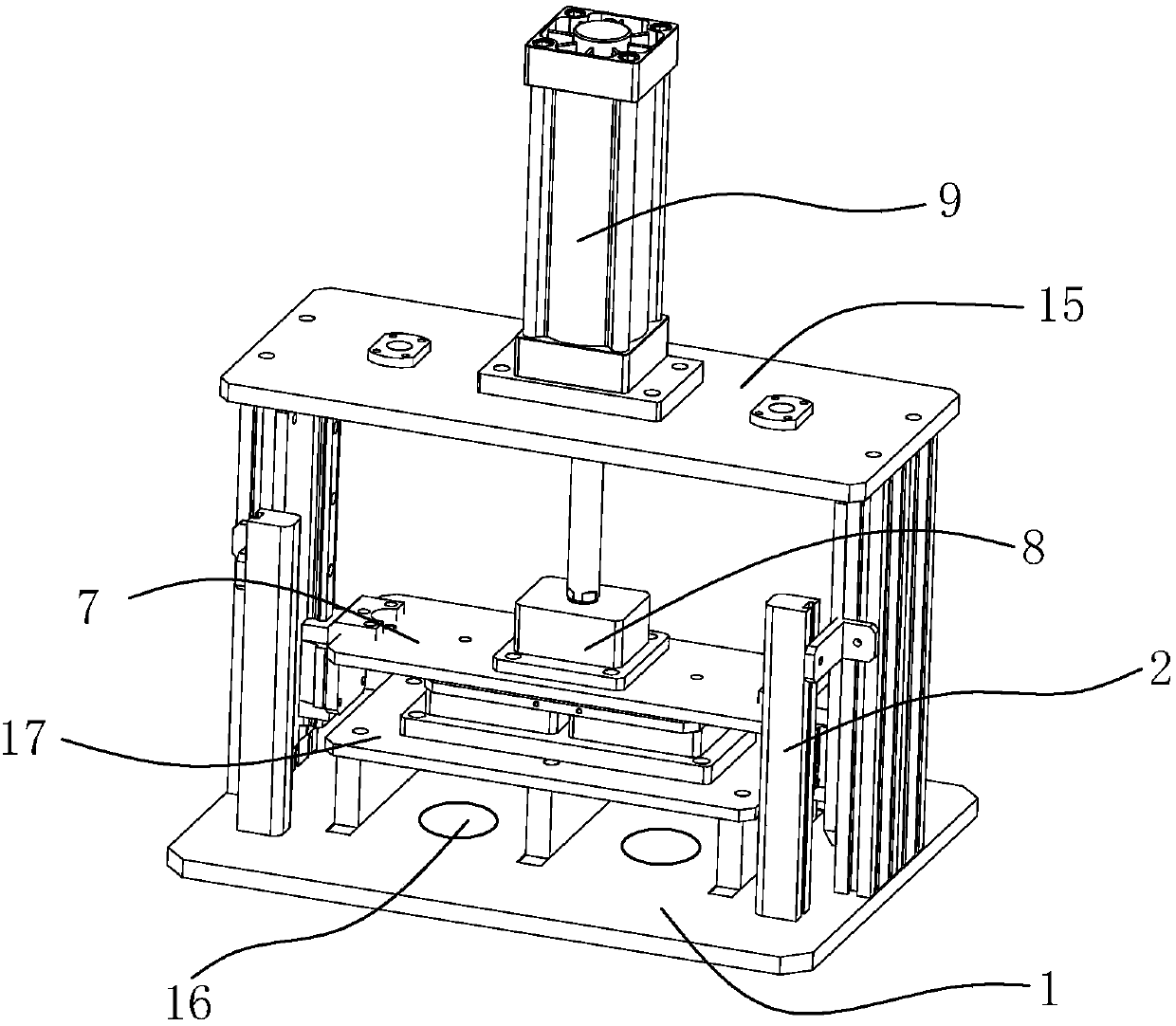
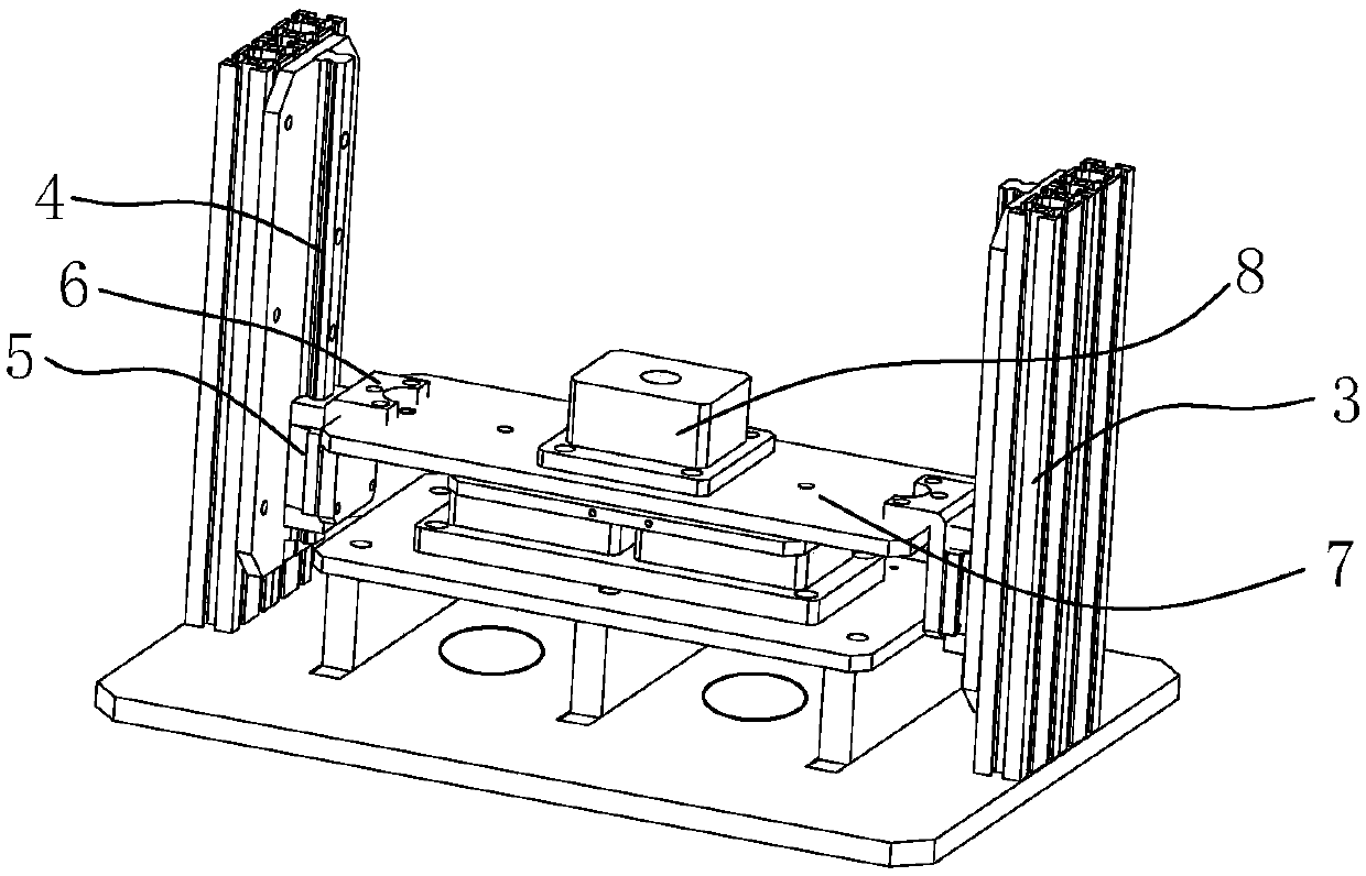
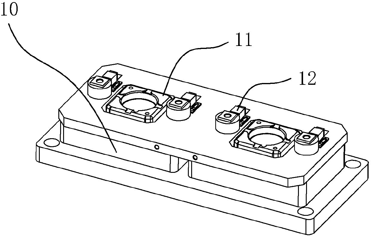
[0019] Embodiment: A cable head manufacturing device that adopts electronic control grating linkage, its main structure includes: base plate 1, grating 2, vertical arm rod 3, rail 4, slider 5, connector 6, pressure plate 7, solder cavity 8. Electric air rod 9, mold box 10, cable clamp 11, tin injection contact 12, tin outlet 13, cable harness ring 14, top cover plate 15, cable channel 16, platform plate 17, the The base plate 1 and the top cover plate 15 are fixed and supported by the vertical arm rod 3; the inner side of the vertical arm rod 3 is fixed with a rail 4, and a slider 5 is mounted on the rail 4, and the slider 5 and the pressure plate 7 pass through the connecting piece 6 Phase fixed;

[0020] The central position of the pressing plate 7 is provided with a solder chamber 8; the central position of the top cover plate 15 is provided with an electric air rod 9, and the end of the electric air rod 9 is fixed on the solder chamber 8; 7 is fixed with a tin-injected co...


PUM


Abstract

The invention relates to a manufacturing device of a cable connector employing electronically controlled grating linkage. A base plate and a top cover plate are fixedly supported through a vertical arm lever; a rail bar is fixed at the inner side of the vertical arm lever; a sliding block is erected on the rail bar and is fixed to a pressure plate through a connector; a soldering tin cavity is arranged at the center position of the pressure plate; an electric gas bar is arranged at the center position of the top cover plate; the tail end of a bar member of the electric gas bar is fixed on the soldering tin cavity; and a tin injection contact is fixed at the lower part of the pressure plate and runs through the soldering cavity through a metal conduit. Tin and a tin flux in the soldering tin cavity can automatically flow into a cable clamp easily through the gravity through the mode that the soldering tin cavity, the tin injection contact, a fixed hole and a tin outlet bath run through one another, so that the cable clamp, a cable chuck and a cable are fused into a whole; a good electric conductor is achieved; and by adopting the working mode that a grating is linked with the electric gas bar, an accident of hand injury caused by misoperation of an operator can be avoided.

Description

technical field [0001] The invention relates to a cable head manufacturing device adopting electric control grating linkage. Background technique [0002] The cable joint is also called the cable head. After the cable is laid, in order to make it a continuous line, each section of the line must be connected as a whole, and these connection points are called cable joints. The cable joints in the middle of the cable line are called intermediate joints, and the cable joints at both ends of the line are called terminal heads. The cable joint is used to lock and fix the incoming and outgoing lines, and play the role of waterproof, dustproof and shockproof. Some electrical installation and construction personnel often do not pay attention to the installation quality when laying wires: no sleeve is installed where the insulating sleeve should be used; no junction box is installed where the junction box should be used; even the splicing method is not used at the wire joint , but ...

Claims


Application Information

Patent Timeline
Patent Type & Authority Patents(China)
IPC IPC(8): H02G1/14
CPCH02G1/14
Inventor 孟圆
Owner 安徽爱谱华顿电子科技有限公司
Why Eureka
Try Eureka