Hall sensor-based fault-tolerant control method of permanent magnet brushless motor

A technology of permanent magnet brushless motor and hall sensor, which is applied in motor control, motor generator control, electronic commutation motor control, etc. It can solve problems such as motor stall, motor sudden stagnation, and technical personnel's life safety threat

Inactive Publication Date: 2017-05-31
HARBIN UNIV OF SCI & TECH
View PDF6 Cites 22 Cited by
  • Summary
  • Abstract
  • Description
  • Claims
  • Application Information

AI Technical Summary

Problems solved by technology

[0003] Based on the Hall position sensor, during the operation of the permanent magnet brushless motor, the Hall failure problem is caused by mechanical vibration and line interface detachment, which makes the motor suddenly stagnate or the motor stalls during normal operation. This failure will cause irreparable problems in production. consequences, even pose a threat to the safety of technicians, therefore, the fault-tolerant control technology based on the Hall position sensor plays a vital role in the actual control system

Method used


Image

  • Hall sensor-based fault-tolerant control method of permanent magnet brushless motor
  • Hall sensor-based fault-tolerant control method of permanent magnet brushless motor
  • Hall sensor-based fault-tolerant control method of permanent magnet brushless motor

Examples


Embodiment Construction

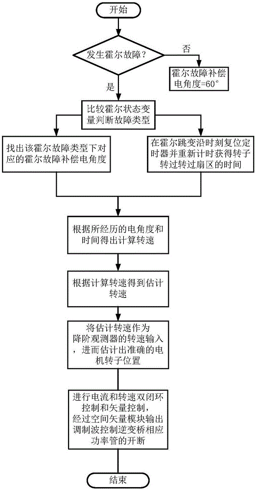
[0045] combine Figure 1~3 To illustrate this embodiment, the permanent magnet brushless motor mentioned in the present invention includes a permanent magnet brushless DC motor and a permanent magnet synchronous motor, and the permanent magnet synchronous motor is used to explain and illustrate the present invention in a specific embodiment. The flow chart of the fault-tolerant control method for the Hall sensor of the permanent magnet brushless motor in this embodiment, as shown in figure 1 As shown, the specific steps are as follows:

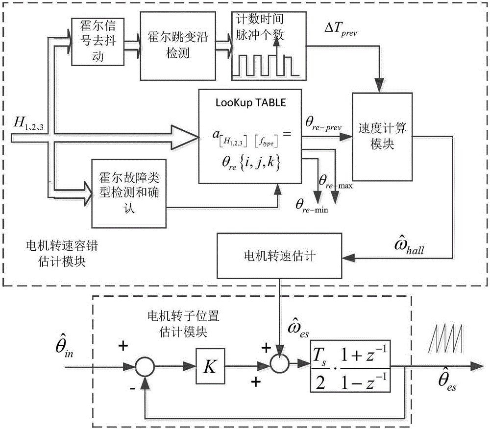
[0046] Step a. At any transition edge of the Hall position signal, determine whether a fault occurs according to the state of the transition edge. If there is no fault, the Hall fault compensation electrical angle θ re-prev Constantly 60°, if there is a failure, go to step b;

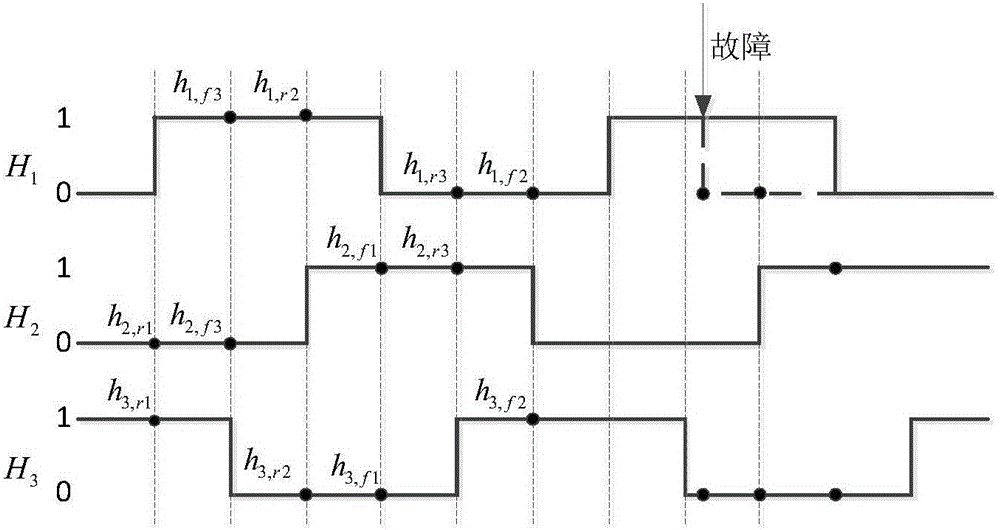
[0047]Step b. Collect the corresponding Hall state variable according to the type of Hall transition edge, and judge the unique Hall fault type according to the Hall...


PUM


Abstract

The invention relates to the field of permanent magnet brushless motor control systems, in particular to a Hall sensor-based fault-tolerant control method of a permanent magnet brushless motor. The invention aims at solving the problem of Hall fault caused by the mechanical vibration and line interface falling off of the motor in an operation process of the permanent magnet brushless motor based on a Hall position sensor. The Hall sensor-based fault-tolerant control method of the permanent magnet brushless motor comprises the steps of determining a Hall jumping edge type at any Hall jumping edge moment, sampling a corresponding Hall state, and determining a concrete Hall fault type; solving fault-tolerant running speed of the motor according to the single-Hall fault type and the double-Hall fault type, and further estimating high-resolution fault-tolerant rotor position information by means of a reduced-order observer so as to carry out the double-closed-loop control for current and running speed as well as vector control; using a space vector module to output a modulated wave so as to control the on and off of a corresponding power tube of an inverter bridge. The Hall sensor-based fault-tolerant control method of the permanent magnet brushless motor is used for single-Hall-sensor or double-Hall-sensor based fault-tolerant control for the permanent magnet brushless motor.

Description

technical field [0001] The invention relates to the field of permanent magnet brushless motor control based on a Hall position sensor, in particular to a Hall sensor fault-tolerant control method for a permanent magnet brushless motor. Background technique [0002] The Hall position sensor is used as the rotor position detection element of the permanent magnet brushless motor. In the control of the brushless DC motor, the Hall sensor provides six commutation positions in each electrical cycle, so as to realize the second, second, and third conduction of the brushless DC motor. Phase six-state control mode; in the control process of permanent magnet synchronous motor, vector control requires high-resolution rotor position information, so Hall position sensors are needed to estimate high-resolution rotor position information. [0003] Based on the Hall position sensor, during the operation of the permanent magnet brushless motor, the Hall failure problem is caused by mechanica...

Claims


Application Information

Patent Timeline
Patent Type & Authority Applications(China)
IPC IPC(8): H02P6/16H02P21/18
CPCH02P6/16H02P2203/03
Inventor 吕德刚都泽源
Owner HARBIN UNIV OF SCI & TECH
Why Eureka
Try Eureka