Method of rapidly calibrating power of high-precision radiofrequency signal source

A technology of radio frequency signal source and calibration method, applied in transmitter monitoring, receiver monitoring and other directions, can solve the problems of long calibration time and complex digital gain control, and achieve the effect of improving speed, fast convergence speed and low calculation amount

Inactive Publication Date: 2017-05-31
成都易慧通科技有限公司
View PDF5 Cites 9 Cited by
  • Summary
  • Abstract
  • Description
  • Claims
  • Application Information

AI Technical Summary

Problems solved by technology

[0006] The purpose of the present invention is to overcome the deficiencies of the prior art, provide a fast calibration method for high-precision radio frequency signal source power, solve the problems of long calibra

Method used


Image

  • Method of rapidly calibrating power of high-precision radiofrequency signal source
  • Method of rapidly calibrating power of high-precision radiofrequency signal source
  • Method of rapidly calibrating power of high-precision radiofrequency signal source

Examples


Embodiment Construction

[0039] The technical solution of the present invention will be further described in detail below in conjunction with the accompanying drawings, but the protection scope of the present invention is not limited to the following description.

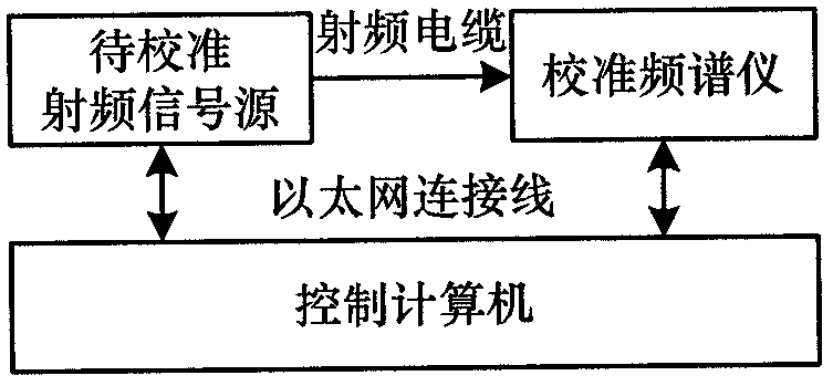
[0040] Such as figure 1 As shown, a high-precision radio frequency signal source power fast calibration method steps are as follows:

[0041] S1. The control computer controls the broadband radio frequency signal source to be calibrated to output monotone signals of different frequency points and power through Ethernet;

[0042] S2, the control computer reads the power measurement result in the calibration spectrum analyzer through Ethernet;

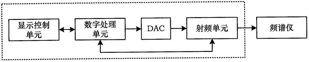
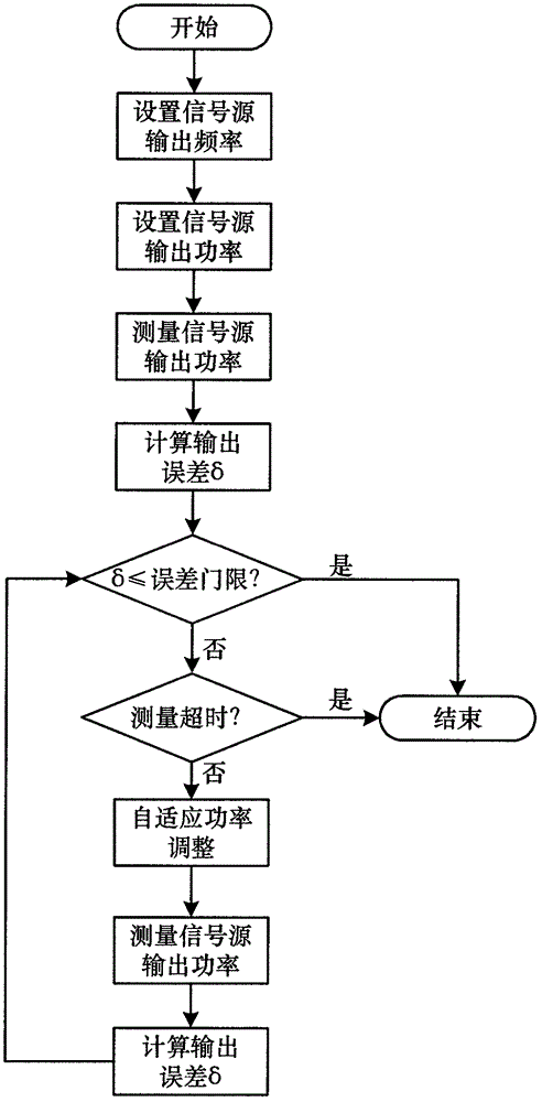
[0043] Such as figure 2 with image 3 As shown, the S2 includes a time synchronization step, a frequency offset estimation step and a synchronization result output step.

[0044] Such as figure 2 , image 3 with Figure 4 , the specific steps of the radio frequency gain and digital gain adjus...


PUM


Abstract

The invention discloses a method of rapidly calibrating power of a high-precision radiofrequency signal source; the method comprises the steps of S1, allowing a control computer to control, through Ethernet, a broadband radiofrequency signal source to be calibrated to output single-tone signals having different frequencies and powers; S2, allowing the control computer to read, through the Ethernet, power measurement results in a calibration spectrometer; S3, allowing the control computer to set output signal frequency and output power for the radiofrequency signal source; allowing the calibration spectrometer to measure the frequency and power of an output signal and reports to the control computer through the Ethernet; allowing the control computer compares the set power value with the measured value of the spectrometer; when the output power precision of the radiofrequency signal source is unsatisfactory, allowing the control computer to adjust the output power of the radiofrequency signal source by means of combined radiofrequency gain and digital gain adaptive spacing search method until the test result of the spectrometer is satisfactory or test is time out, and recording final power setting parameters of the radiofrequency signal source. Compared with linear search methods, the adaptive spacing search method has lower calibration load and greatly shorter calibration time under wide-range frequency domain coverage.

Description

technical field [0001] The invention relates to the technical field of radio testing, in particular to a high-precision radio frequency signal source power calibration technology. Background technique [0002] The radio frequency signal source is used to generate radio frequency signals with certain characteristics, and is one of the key instruments in radio measurement and testing. Modern signal sources can be divided into analog RF and digital RF signal sources. The analog radio frequency signal source mainly generates continuous wave, AM, FM, PM and other signals; the digital vector radio frequency signal source can generate various digital modulation signals in addition to the function of the analog radio frequency signal source, such as QPSK, QAM and other signals commonly used in wireless communication . [0003] With the increase of radio equipment's demand for frequency resources, the frequency coverage of radio frequency signal sources is getting wider and wider, ...

Claims


Application Information

Patent Timeline
IPC IPC(8): H04B17/11H04B17/21
CPCH04B17/11H04B17/21
Inventor 韩建
Owner 成都易慧通科技有限公司
Why Eureka
Try Eureka