Correction method and device for scanned image
A technology for scanning images and images, applied in the field of image processing, can solve problems such as poor quality of scanned images, and achieve the effects of increasing hardware costs, reducing dependencies, and improving quality
- Summary
- Abstract
- Description
- Claims
- Application Information
AI Technical Summary
Problems solved by technology
Method used
Image
Examples
Embodiment 1
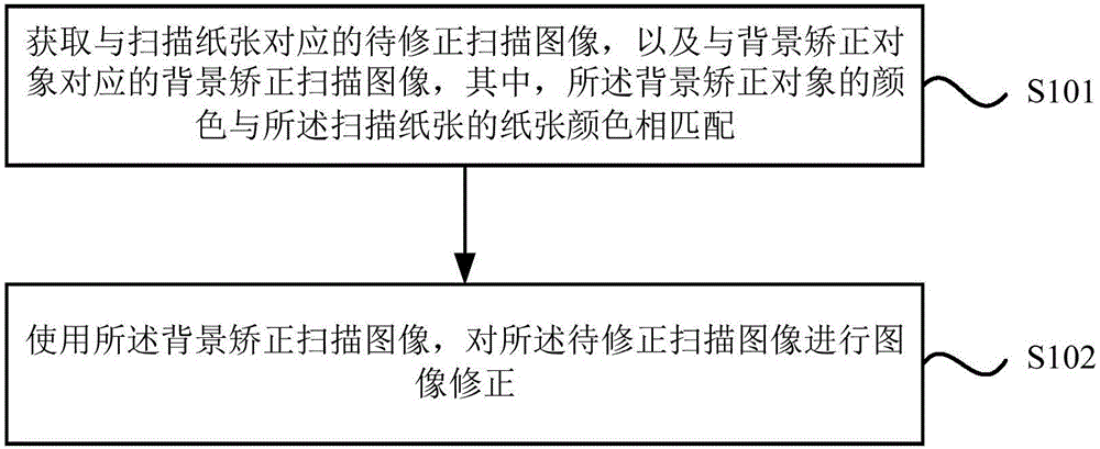
[0054] figure 1 It is a flow chart of a method for correcting a scanned image provided by Embodiment 1 of the present invention. This embodiment is applicable to the situation where the brightness of a scanned image is corrected by a scanning device to be uneven or unclear. The device can be implemented by means of software and / or hardware, and generally can be integrated into a scanning device.
[0055] The method of Embodiment 1 of the present invention specifically includes:
[0056]S101. Acquire a scanned image to be corrected corresponding to the scanned paper, and a background corrected scanned image corresponding to a background corrected object, wherein the color of the background corrected object matches the paper color of the scanned paper.
[0057] In this embodiment, the scanned image to be corrected corresponding to the scanned paper and the background corrected scanned image corresponding to the background corrected object can be obtained by scanning with a scan...
Embodiment 2
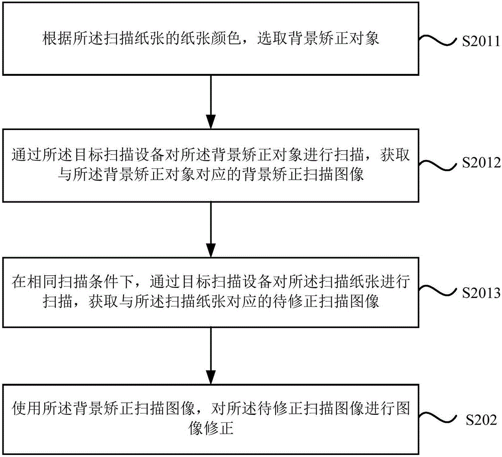
[0062] figure 2 It is a flow chart of a method for correcting a scanned image provided by Embodiment 2 of the present invention. Embodiment 2 of the present invention is optimized on the basis of Embodiment 1, specifically for obtaining the scanned image to be corrected corresponding to the scanned paper, and A background corrected scanned image corresponding to the background corrected object, wherein the color of the background corrected object matches the paper color of the scanned paper for further optimization of the operation, such as figure 2 As shown, the second embodiment of the present invention specifically includes:
[0063] S2011. Select a background correction object according to the paper color of the scanned paper.
[0064] Wherein, the background correction object may be a blank paper with the same paper color as the scanned paper, or may also be a special document scanning table that matches the paper color of the scanned paper.
[0065] S2012. Scan the b...
Embodiment 3
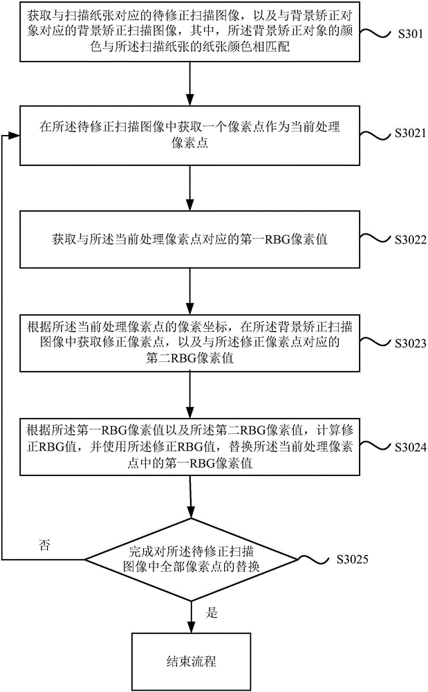
[0075] image 3 It is a flow chart of a scanning image correction method provided by Embodiment 3 of the present invention. Embodiment 3 of the present invention is optimized and improved on the basis of the above-mentioned embodiments. For using the background to correct the scanned image, for the to-be-corrected Scanned images for image correction are further described as image 3 As shown, the method of the third embodiment of the present invention specifically includes:
[0076] S301. Acquire a scanned image to be corrected corresponding to the scanned paper, and a background corrected scanned image corresponding to a background corrected object, wherein the color of the background corrected object matches the paper color of the scanned paper.
[0077] S3021. Obtain a pixel point in the scanned image to be corrected as a currently processed pixel point.
[0078] S3022. Acquire a first RGB pixel value corresponding to the currently processed pixel.
[0079] S3023. Accord...
PUM
 Abstract
Description
Claims
Application Information
 - R&D
- Intellectual Property
- Life Sciences
- Materials
- Tech Scout
- Unparalleled Data Quality
- Higher Quality Content
- 60% Fewer Hallucinations
Browse by: Latest US Patents, China's latest patents, Technical Efficacy Thesaurus, Application Domain, Technology Topic, Popular Technical Reports.
© 2025 PatSnap. All rights reserved.Legal|Privacy policy|Modern Slavery Act Transparency Statement|Sitemap|About US| Contact US: help@patsnap.com


