
Regeneration method for exhaust-gas aftertreatment device in engine-driven compressor, and engine-driven compressor provided with said aftertreatment device

An exhaust after-treatment, engine-driven technology, applied in exhaust devices, engine components, engine control and other directions, can solve problems such as increased exhaust resistance, inability to maintain active temperature, damage to the main body and filter element, and avoid damage. Effect

Active Publication Date: 2017-05-31
HOKUETSU IND
View PDF8 Cites 2 Cited by
  • Summary
  • Abstract
  • Description
  • Claims
  • Application Information

AI Technical Summary

Problems solved by technology

[0024] In this regard, when repeating the operation of high-load operation for a very short time during low-load operation and then returning to low-load operation, the fuel injection amount of the post injection increases or decreases with load fluctuations, or repeats the operation during temporary high-load operation. The post-injection stop operation, so the temperature of the oxidation catalyst becomes unstable, and cannot maintain the state above the activation temperature, because NO can not be stably / sustained 2 , so PM cannot be combusted, or, although the forced regeneration is being performed, if the operator stops the engine, the PM combustion is also stopped, so not only the filter element cannot be regenerated, but the accumulation of PM will also increase, despite the forced regeneration (Load fluctuation type forced regeneration) function, but a large amount of PM accumulates on the filter element, which leads to an increase in exhaust resistance. When the exhaust temperature rises abnormally and reaches the self-ignition temperature of PM, a large amount of accumulated PM spontaneously ignites rapidly, and the DPF main body and filter element are damaged. danger

Method used


Image

  • Regeneration method for exhaust-gas aftertreatment device in engine-driven compressor, and engine-driven compressor provided with said aftertreatment device
  • Regeneration method for exhaust-gas aftertreatment device in engine-driven compressor, and engine-driven compressor provided with said aftertreatment device
  • Regeneration method for exhaust-gas aftertreatment device in engine-driven compressor, and engine-driven compressor provided with said aftertreatment device

Examples


Embodiment Construction

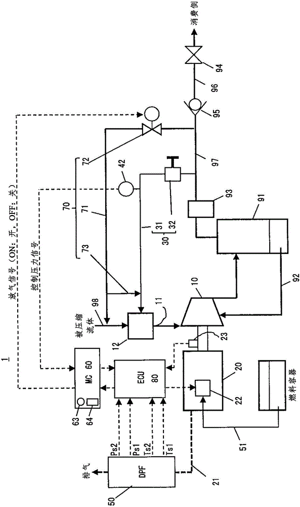
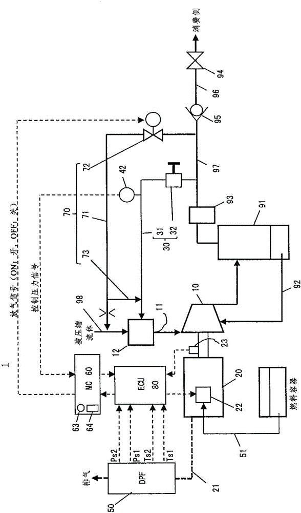
[0079] Hereinafter, the engine-driven compressor 1 of the present invention will be described with reference to the drawings.

[0080] [Constant load type forced regeneration]

[0081] In the forced regeneration method of the DPF performed in the present invention, "constant load type forced regeneration" performed in a state in which load fluctuations of the engine are excluded is adopted.

[0082] In the "constant load type forced regeneration", in order to obtain the optimum exhaust gas temperature / flow rate so that the oxidation catalyst is kept at the active temperature, a predetermined regeneration speed is set as the engine speed at the time of forced regeneration, Also, the main injection amount of fuel for maintaining the regenerative rotational speed is set in advance, and the fuel injection amount of the additional injection for raising the temperature of the oxidation catalyst is also set in advance.

[0083] The constant load type forced regeneration adopted in t...


PUM


Abstract

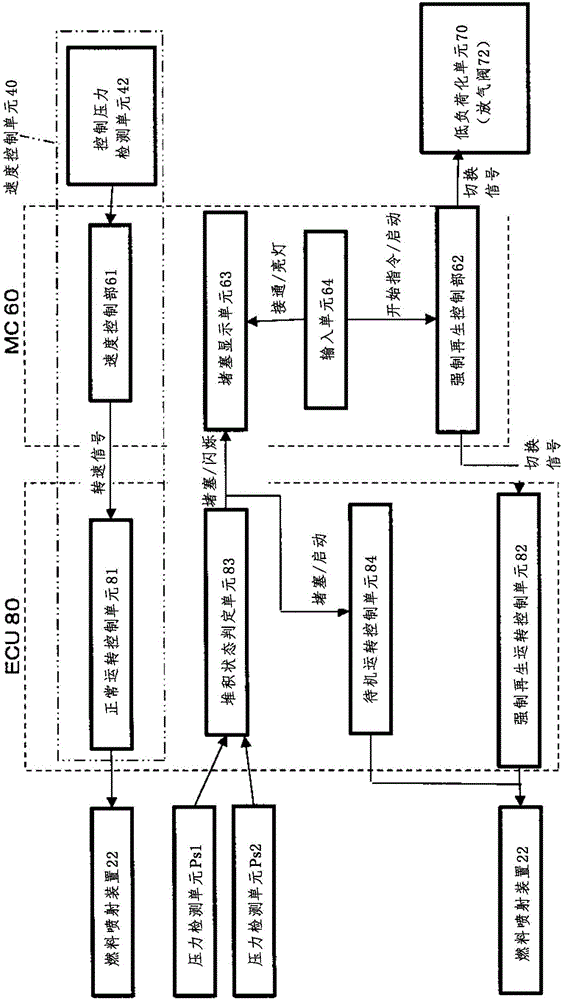
Provided is a forced-regeneration treatment method for a DPF that can be used in an engine-driven compressor. When the amount of particulate matter (PM) deposited in a filter element of an exhaust-gas aftertreatment device (DPF) 50, which is provided in an exhaust path 21 of an engine 20 that is provided in an engine-driven compressor 1, becomes equal to or greater than a predetermined forced-regeneration start amount (e.g., 10 g / L) and a forced-regeneration start command is input, a capacity controlling means 30 of the engine-driven compressor 1 is disabled to close an intake valve 12 and to open the discharge side of a compressor main unit 10 to atmospheric pressure, thereby causing the compressor main unit 10 to achieve a low-load state. In addition, the operation mode of the engine is switched to a predetermined forced-regeneration mode to operate the engine at a predetermined regeneration rotation speed and to increase the temperature of the exhaust gas. Thus, the temperature inside the DPF 50 is increased to a temperature equal to or higher than the temperature at which an oxidative catalyst is activated and to a temperature lower than the self-combustion temperature of the PM, thereby forcibly burning the PM deposited in the filter element.

Description

technical field [0001] The present invention relates to an engine-driven compressor equipped with an exhaust gas post-treatment device, and more specifically, relates to a method for collecting particulate matter (particulate matter (hereinafter referred to as "PM") captured on a filter element provided in the exhaust gas post-treatment device. ”) A method of regenerating the filter element by burning and removing it, and an engine-driven compressor having a structure for performing the regenerating method. Background technique [0002] The engine-driven compressor that drives the main body of the compressor with an engine can obtain compressed air even when the power supply is difficult to secure, especially the packaged type that integrates the main body of the compressor, the engine, and other necessary equipment in a soundproof box Engine-driven compressors are widely used as compressed air supply sources in civil engineering and construction sites because they are easy ...

Claims


Application Information

Patent Timeline
Patent Type & Authority Applications(China)
IPC IPC(8): F01N3/023F01N3/025F01N3/029F01N3/18F04B35/00F04B49/00F04B49/02
CPCF02D29/04F02D41/029F02D41/1441F02D41/1446F02D41/1448F02D41/405F02D2200/0812F04B35/002F04B49/065F04B49/225F04B2203/0605Y02T10/40F01N3/025F01N3/106F02D9/02F02D2009/023
Inventor 早川賛
Owner HOKUETSU IND
Learn More