Piston pump with outlet valve in the piston

A technology of piston pumps and outlet valves, which is applied to parts, pumps, and pump components of elastic fluid pumping devices, and can solve problems such as gasification and precipitation of fuel, reduction of transmission power, and reduction of piston pump transmission power. , to achieve the effects of reduced suction negative pressure, reduced dead volume, and reduced manufacturing costs

Active Publication Date: 2020-09-08
ROBERT BOSCH GMBH
View PDF7 Cites 0 Cited by
  • Summary
  • Abstract
  • Description
  • Claims
  • Application Information

AI Technical Summary

Problems solved by technology

High suction negative pressure reduces the delivery power of the pump
In addition, the high suction vacuum can also lead to gasification of the sucked-in fuel, and the resulting volume flow of the fuel can suddenly occur
In addition to the factors already mentioned, this also reduces the delivery power of the piston pump

Method used


Image

  • Piston pump with outlet valve in the piston
  • Piston pump with outlet valve in the piston
  • Piston pump with outlet valve in the piston

Examples


Embodiment Construction

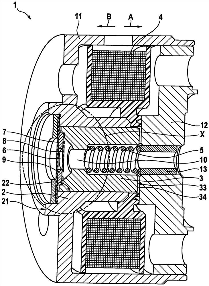
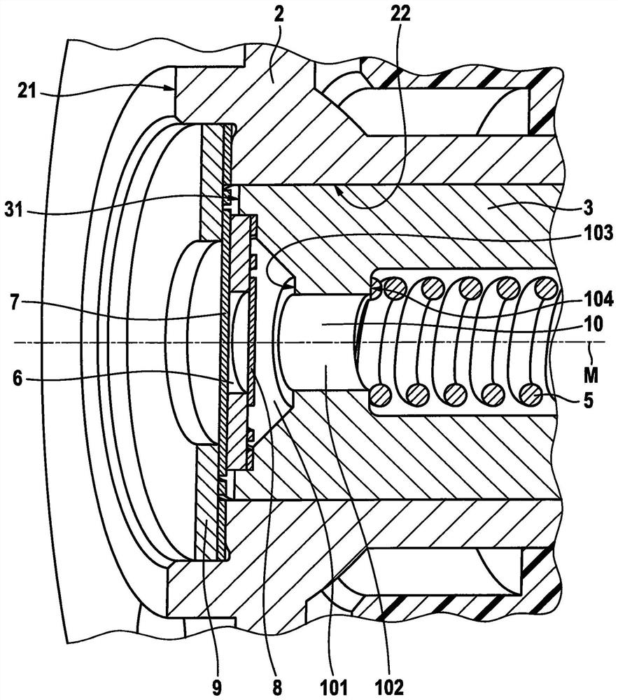
[0024] Refer below Figure 1a )and Figure 1b ) describes in detail the piston pump 1 according to a preferred embodiment of the present invention. exist Figure 1b ), in Figure 1a ) is shown enlarged.

[0025] Such as Figure 1a ) as can be seen, the piston pump 1 according to the invention is constructed in the form of an electromagnetic piston pump and correspondingly has a cylinder 2, a piston 3 arranged in the cylinder 2, as an actuator 4 to move in a first direction (arrow A) A solenoid operating the piston 3 and a spring acting as a return element 5 to move the piston 3 in the second direction (arrow B) up to its initial position. Furthermore, the fuel pump 1 according to the invention has a first inlet valve 7 , an outlet valve 8 and a compression chamber 6 . The components of the piston pump 1 are surrounded by a housing 11 and an armature plate 12 .

[0026] During the suction phase, the solenoid coil 4 is energized and the piston 3 is moved within the cylinder ...


PUM


Abstract

The invention relates to a piston pump, in particular for fuel injection systems for motorcycles and / or small combustion engines. The piston pump comprises: a cylinder, which has a cylinder base and cylinder walls; a piston arranged in the cylinder; an actuator which moves the piston in a first direction in the cylinder; a restoring element, in particular a spring, which moves the piston in a second direction in the cylinder, the second direction being opposite to the first direction; a compression chamber, which is delimited by the piston, the cylinder base and the cylinder walls; an intake valve through which a fuel flows into the compression space; and an exhaust valve through which the fuel flows from the compression space, wherein the inlet valve being arranged in the cylinder base and the outlet valve being arranged in the piston.

Description

technical field [0001] The present invention relates to a piston pump for fuel injection systems of small motorcycles, such as scooters, snowmobiles, quads, jet skis or the like, or other small motor applications, such as chainsaws. Background technique [0002] Such a piston pump is disclosed, for example, in document GB 2478876B. This relates to a piston pump, in particular an electromagnetic piston pump, with a piston, an actuator for actuating the piston, a reset element for returning the piston to an initial position, an inlet valve, a compression chamber and an outlet valve . By actuating the piston, fuel is sucked into the compression chamber through the inlet valve in the suction phase. During the compression phase, fuel is delivered from the compression chamber through the outlet valve. [0003] In piston pumps according to the prior art, the inlet valve and the outlet valve are arranged coaxially with one another on the same side of the compression chamber. In ...

Claims


Application Information

Patent Timeline
Patent Type & Authority Patents(China)
IPC IPC(8): F04B53/12F04B53/10F02M59/10F02M59/46
CPCF02M59/10F02M59/46F02M59/462F04B53/10F04B53/129F02M51/04F02M59/025F04B17/046F04B53/123
Inventor A·普利施F·尼切J·科雷克J·吉斯勒S·芙洛T·阿尔盖尔W·莫伊雷尔W·施特罗尔
Owner ROBERT BOSCH GMBH
Why Eureka
Try Eureka