

Dehumidifying device capable of rapidly drying air in hydropower station operating room
A fast drying, hydropower technology, applied in air conditioning systems, space heating and ventilation, household heating, etc., can solve problems affecting the normal operation of electrical equipment in hydropower plants, heat exchanger humid air erosion and oxidation, heat exchanger damage, etc. , to ensure the dehumidification efficiency, improve the connection stability, and ensure the effect of favorable support
- Summary
- Abstract
- Description
- Claims
- Application Information
AI Technical Summary
Problems solved by technology
Method used
Image

Examples
Embodiment 1
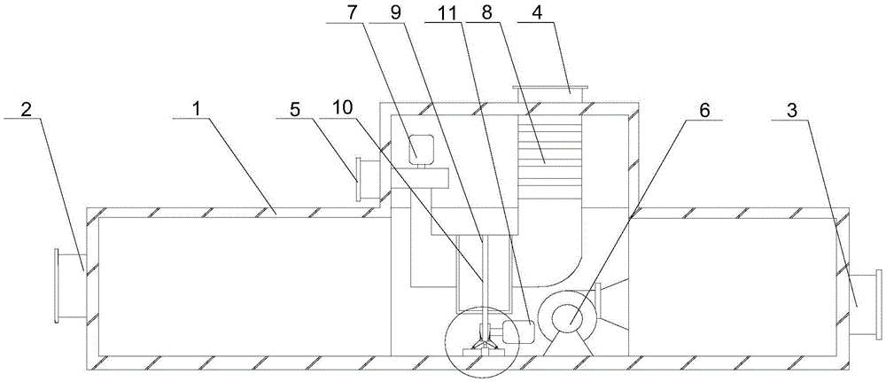
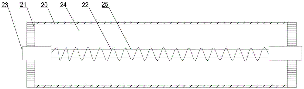
[0023] Such as Figure 1 to Figure 4 As shown, the present invention can quickly dry the dehumidification device of the air in the operating room of the hydropower station, comprising a casing 1, on which the casing 1 is provided with an air inlet 2, an air outlet 3, a regeneration inlet 4 and a regeneration outlet 5, so that A fan 6, a heater 8, a dehumidification wheel 9 and a regeneration fan 7 are installed in the casing 1, one end of the fan 6 communicates with the air inlet 2, the other end of the fan 6 is connected with the air outlet 3, and the motor 11 The output end of the heater is connected with a pulley 12, and the heater 8 communicates with one end of the regeneration air inlet 4, the dehumidification wheel 9 and the regeneration blower 7 respectively, and the other end of the regeneration blower 7 communicates with the regeneration outlet 5, and the heating The device 8 includes a cylindrical body with openings at both ends, a heating wire 22, a terminal post 23...
Embodiment 2
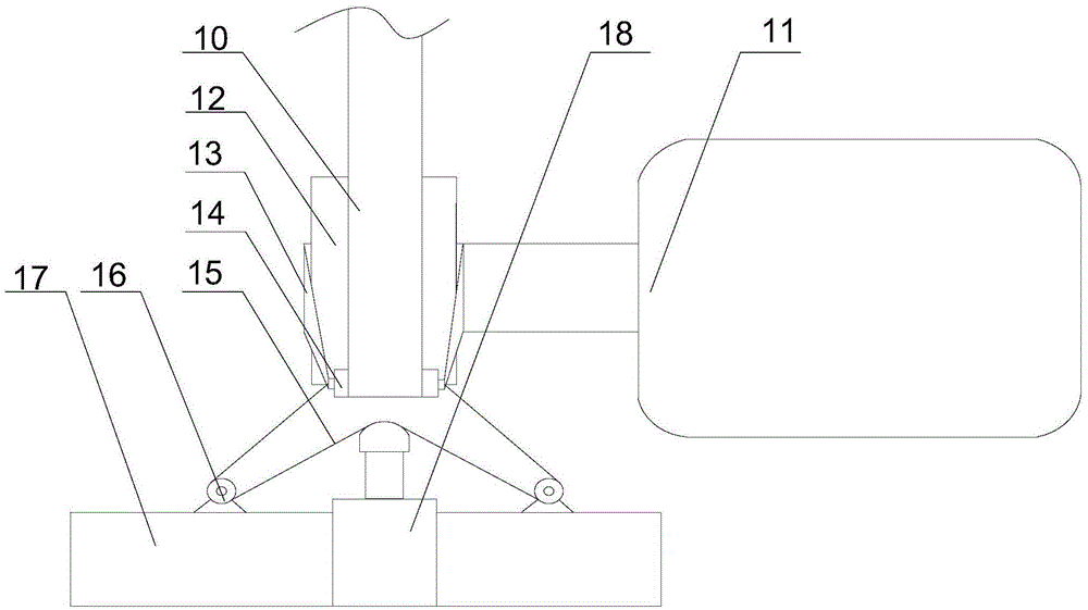
[0026] Such as figure 2 and Figure 4 As shown, in this embodiment, on the basis of Embodiment 1, the roller 14 arranged tangentially to the pulley 12, the pulley 12, the roller 14 and the dehumidification runner 9 are connected by the belt 10, and the roller 14 and the belt 10 A pressure sensor 19 is installed at the tangent, and the pulley 12 is connected with the roller 14 by a connecting rod 13. A support 17 is arranged in the casing. A cylinder 18 and a plurality of fixed pulleys 16 are installed on the support 17. The pressure sensor 19 is connected with the The driving device of the cylinder 18 is connected, and a plurality of fixed pulleys 16 are symmetrically arranged on both sides of the output end of the cylinder 18. The two ends of the rotating shaft of the roller 14 are connected with a traction line 15, and the traction line 15 bypasses the two fixed pulleys 16 and the cylinder 18 The output end forms a pulley block. The motor 11 drives the dehumidification ru...
Embodiment 3
[0028] Such as Figure 4 As shown, this embodiment is based on Embodiment 1, the connecting rod 13 is an elastic plastic rod, and the two ends of the elastic plastic rod are sleeved on the rotating shafts of the pulley 12 and the roller 14 respectively. In order to prevent the roller 14 from moving with the belt 10 when rotating, the connecting rod 13 connects the pulley 12 to the roller 14. When the roller 14 is pulled at the output end of the cylinder 18, the connecting rod 13 made of elastic plastic will produce a small deformation to The movement of the rollers 14 is accommodated while ensuring favorable support of the rollers 14 .
PUM
 Abstract
Description
Claims
Application Information