
Dewatering bucket

A technology of dewatering bucket and supporting shell, applied in the field of dewatering bucket, can solve problems such as poor cleaning effect, and achieve the effect of simple structure and good cleaning effect

Inactive Publication Date: 2017-06-09
YUYAO JIJIA ELECTRICAL APPLIANCES
View PDF0 Cites 0 Cited by
  • Summary
  • Abstract
  • Description
  • Claims
  • Application Information

AI Technical Summary

Problems solved by technology

[0004] The problem to be solved by the present invention is to provide a dehydration barrel to overcome the defects of poor cleaning effect in the prior art

Method used


Image

  • Dewatering bucket

Examples


Embodiment Construction

[0011] The specific implementation manners of the present invention will be further described in detail below in conjunction with the accompanying drawings and embodiments. The following examples are used to illustrate the present invention, but are not intended to limit the scope of the present invention.

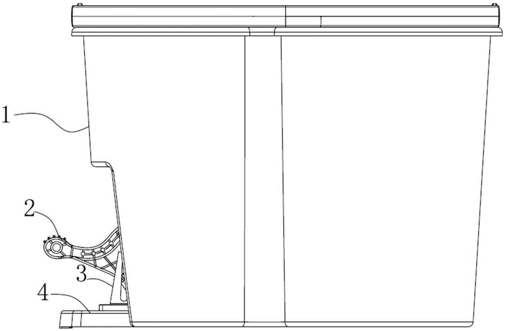
[0012] Such as figure 1 As shown, a dehydration barrel of the present invention includes a housing 1, a tray 2 and a supporting shell 3, the tray 2 and the supporting shell 3 are arranged in the housing 1, and there is a groove in the housing 1, and the The bottom surface of the tray 2 is affixed to the upper end of the rotating shaft, the rotating shaft is built into the groove, the surface of the tray 2 is mesh-shaped, and a transmission mechanism is arranged under the supporting shell 3; the upper end of the transmission shaft in the transmission mechanism Fixed together with the bottom surface of the supporting shell 3, the tray 2 includes a buckle 4 and a sealing rin...


PUM


Abstract

The invention provides a dehydration barrel, which includes a shell, a tray and a supporting shell. The tray and the supporting shell are arranged in the shell. There is a groove in the shell. The bottom surface of the tray is fixed to the upper end of the rotating shaft. The shaft is built in the groove, the surface of the tray is mesh-shaped, and a transmission mechanism is arranged under the support shell; the upper end of the transmission shaft in the transmission mechanism is fixedly connected with the bottom surface of the support shell, and the tray includes a The energized buckle and the sealing ring, the buckle and the inner sleeve of the sealing ring are respectively assembled and fixed with the housing from two opposite directions. The invention has simple structure and good cleaning effect.

Description

technical field [0001] The invention relates to a dehydration bucket. Background technique [0002] At present, in family life and work, mop is requisite daily necessities, and what existing domestic general use is automatic dehydration barrel to clean and dehydration mop. The existing dehydration bucket has poor cleaning effect. Contents of the invention [0003] (1) Technical problems to be solved [0004] The problem to be solved by the present invention is to provide a dehydration bucket to overcome the defect of poor cleaning effect in the prior art. [0005] (2) Technical solution [0006] In order to solve the technical problem, the present invention provides a dehydration bucket, which includes a shell, a tray and a support shell, the tray and the support shell are arranged in the shell, there is a groove in the shell, and the bottom surface of the tray is fixed to rotate The upper end of the shaft, the rotating shaft is built in the groove, the surface of the ...

Claims


Application Information

Patent Timeline
IPC IPC(8): A47L13/58
CPCA47L13/58
Inventor 应吉安
Owner YUYAO JIJIA ELECTRICAL APPLIANCES
Features
  • Generate Ideas
  • Intellectual Property
  • Life Sciences
  • Materials
  • Tech Scout
  • Unparalleled Data Quality
  • Higher Quality Content
  • 60% Fewer Hallucinations
Learn More