Microwave ablation device

A microwave ablation and microwave generation technology is applied in the field of medical devices to achieve the effects of effective utilization, reducing the probability of causing complications, and reducing diameter requirements

Active Publication Date: 2017-06-09
HANGZHOU BRONCUS MEDICAL CO LTD
View PDF11 Cites 5 Cited by
  • Summary
  • Abstract
  • Description
  • Claims
  • Application Information

AI Technical Summary

Problems solved by technology

Therefore, only thinner coaxial cables can be selected to transmit microwave energy

Method used


Image

  • Microwave ablation device
  • Microwave ablation device
  • Microwave ablation device

Examples


Embodiment 1

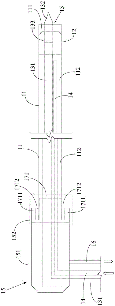
[0032] refer to figure 1 As shown, the water blocking structure 12 is a water blocking plug sliding in the hollow sheath tube 11, the water blocking plug can be made of rubber material, and the outer wall is coated with a lubricating material. The side of the water blocking plug is blocked in the hollow sheath 11 to play a role of water blocking, and the water blocking plug separates the interior of the hollow sheath 11 to form a microwave ablation space 111 and a water return space 112 . The water blocking plug is provided with a sealing socket for the insertion of the microwave generating structure 13. The microwave generating structure 13 is inserted on the water blocking plug through the sealing socket. The microwave generating structure 13 is mainly composed of a coaxial cable 131 and a coaxial cable 131 The microwave antenna head 132 of the first end is formed, and the water blocking plug is arranged at the junction of the coaxial cable 131 and the microwave antenna head...

Embodiment 2

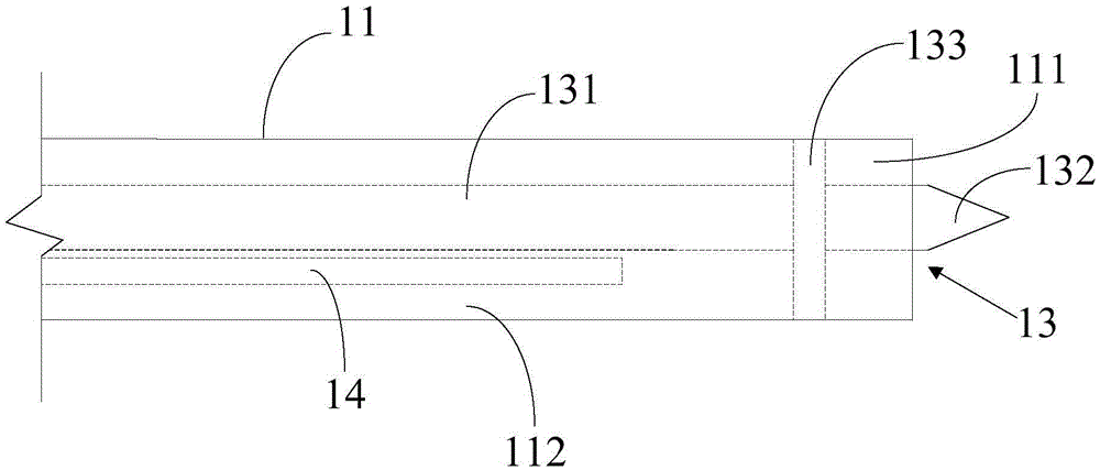
[0034] refer to image 3 As shown, the microwave generating structure 13 is composed of a coaxial cable 131, a microwave antenna head 132 and an insulating layer 133. The insulating layer 133 is arranged between the first end of the coaxial cable 131 and the microwave antenna head 132. The side of the insulating layer 133 The part extends outwards and is blocked in the hollow sheath tube 11 and can move along the hollow sheath tube 11. The insulating layer 133 can be directly used as a water blocking structure to simplify the structure. It can also play a role in water blocking and make the coaxial cable 131 and microwave The antenna head 132 moves along the hollow sheath 11 .

[0035] The following are examples of the two joint components of the microwave ablation device of the present invention:

[0036] Example 1:

[0037] In this embodiment, the hollow sheath is a conductive material, which supports the ablation treatment of fixed microwave generating structures.

[003...


PUM


Abstract

The invention discloses a microwave ablation device, which comprises a hollow sheathing canal, a water blocking structure, a microwave generating structure and a connector assembly, wherein the water blocking structure is movably sealed and blocked in the hollow sheathing canal; the microwave generating structure is inserted and arranged on the water blocking structure, and comprises a coaxial cable and a microwave antenna head arranged at the end part of the coaxial cable; the connector assembly is sealed and plugged at the end part of the hollow sheathing canal; a cooling water inlet pipe and a cooling water return pipe for communicating the hollow sheathing canal are respectively connected onto the connector assembly. The hollow sheathing canal which is matched with a puncture needle and a biopsy needle to be used is directly used as an outer sheathing canal for microwave ablation; the original microwave generation structure arranged inside the microwave needle is glidingly arranged in the hollow microwave ablation through the water blocking structure; the space inside the hollow sheathing canal can be more effectively utilized; the requirement on the diameter of the hollow sheathing canal during the microwave ablation can be reduced; the complication causing probability is reduced.

Description

technical field [0001] The invention relates to the field of medical devices, in particular to a microwave ablation device. Background technique [0002] Microwave ablation technology has a wide range of clinical application prospects due to its fast ablation speed, stable ablation range, and protection of large blood vessels. Its application fields include tumors of liver, kidney, pancreas, lung, breast, thyroid and other organs, ablation of benign nodules, closure of varicose veins, ablation of atrial fibrillation, renal artery sympathetic nerve blockade for refractory hypertension, etc. . Especially for the ablation of abdominal organs, such as liver, kidney, pancreas and lung tumors, the clinical effect is very significant. [0003] In the clinical application of tumor ablation, sometimes a puncture needle and a hollow sheath are first used to reach the tumor site to establish a working channel. Keep the hollow sheath, and after pulling out the puncture needle, use a ...

Claims


Application Information

Patent Timeline
Patent Type & Authority Applications(China)
IPC IPC(8): A61B18/18
Inventor 孙非张鹏周丽
Owner HANGZHOU BRONCUS MEDICAL CO LTD
Why Eureka
Try Eureka