Gas Removal Apparatus and Related Methods

a technology of gas removal apparatus and gas removal chamber, which is applied in the direction of intravenous devices, instruments, other medical devices, etc., can solve the problems of air pockets which can be detrimental to the instrument or process, create problems, problems, and negatively affect the outcome of the process or product, and achieve the effect of convenient re-filling

Active Publication Date: 2019-01-17
AILNH LLC
View PDF7 Cites 2 Cited by
  • Summary
  • Abstract
  • Description
  • Claims
  • Application Information

AI Technical Summary

Benefits of technology

[0014]In another embodiment of the present disclosure, an air removal device having a compact assembly designed to remove air from intravenous fluid tubing systems is provided. When air is introduced or occurs in a tubing system, it can lead to patient risk (embolism) or, at the very least, require the attention of the nursing staff. This embodiment of the present disclosure mitigates these concerns by allowing air to become separated from the fluid before being introduced into a patient. This embodiment is connected in-line with any IV tubing set as the last component before the pump (or patient, if the system is gravity fed). A clip feature at the top of the device attaches to the IV tubing to ensure the recommended orientation. Any air in the system is separated from the fluid as it enters the chamber. When air enters the chamber, it rises through the fluid to the top of the chamber and displaces a small amount of fluid. If necessary, after a large amount of air has been captured, the device can be refilled with fluid by attaching a syringe or other object or device to the valve and drawing out the air, which simultaneously refills the chamber with fluid. This allows the device to be easily refilled without removal from the pump for re-priming.
[0016]The present disclosure has many benefits over the current standard practices in the industry. First, the present disclosure allows for a larger capacity to hold more air as it is removed from the fluid and to hold more fluid. This would allow for less required maintenance, reducing costs and time. The present disclosure also allows for a reduction in costs in the development, manufacturing, maintenance, and upkeep of an air removal device by using less parts, no electricity in the device, no complicated and complex integrated parts that can break, and no obstructions in the chamber where the fluid flows into, where more viscous fluids can impede the evacuation of air or the obstructions can wear down or fail over time. The present disclosure also allows for an apparatus to have a refillable apparatus, so that captured air can be removed and replaced with fluid by extracting the air through a valve in the device. The present disclosure also allows a clip at the top of the device to ensure proper orientation of the device and the tube. The present disclosure also allows for a lower diameter than the current methods and systems for priming of similar apparatuses. For instance, priming for the apparatus in the present disclosure could be done at a minimum diameter of 0.35″ but diameters significantly less than 0.35″ prevented the apparatus from priming properly or easily. The present disclosure also allows for diameter, length, and volume variations depending on context and application and depending on capturing requirements. The present disclosure also allows for easy manufacturing using multiple processes and materials, such as using molded plastic or machined material using only basic operations, and provides an apparatus and method that does not require the use of components that can fail due to wear or the air or gas being a larger or entering into the chamber in a more turbulent manner than expected.

Problems solved by technology

Gas found in lines, such as intravenous fluid lines, hydraulic lines, water lines or pipes, or car fluid systems such as oil and brakes, often times forms air pockets which can be detrimental to the instrument or process.
Problems associated with gas (often air) entering into a line is a problem that exists in various industries and services, including but not limited to, medical, research, laboratories, manufacturing, avionics, colonics, chemotherapy, and any other field or purpose where the introduction of a gas creates issues, problems, or negatively effects outcome of the process or product.
Further, in current technologies and devices, liquid frequently gets trapped in the devices when the bag is empty.
Air trapped in vessels providing blood to the lungs can inhibit pulmonary circulation and cause chest pain and rapid breathing.
In some patients, the air may pass to the left side of the heart and on to the brain or the coronary arteries, which can lead to more serious complications.
A 50 ml of air can cause hypotension and dysrhythmias, while a 300 ml of air can cause death if introduced rapidly.
Generally, this occurs due to circulatory obstruction and cardiovascular collapse.
Further, litigation costs and expenses can be in the millions of dollars as CMS has designated air embolisms as a “Never Event”—a serious and costly error in the provision of health care services that should never happen, and because of the designation as a “Never Event,” the hospital or other provider must bear the responsibility and cost.
Many of them require the use of complicated devices that attempt to solve the problem by having one or more sensors that detect air and cause an alarm to go off if air is detected in the line.
While the alarms can be helpful, it does not solve the problem of preventing air from being introduced into the system or patient and creates other problems, some of which are discussed below.
Other solutions to preventing air bubbles from being introduced into the blood often involve complicated devices that often are not completely successful and have components that wear out over time.
This practice consumes valuable time for the caregiver, increases costs associated with successful care giving, and, often times, creates an alarm fatigue for the caregiver, which is a serious recognized problem in the healthcare field.
Current solutions are limited in various ways, including but not limited to, the capacity to hold air and fluid (where the current standard protocols are to remove the IV set after 72-96 hours), allowing more air bubbles to form, are limited in being non-refillable, and can sometimes move or relocate causing air to be introduced into the line.
When air is introduced or occurs in a tubing system, it can lead to patient risk (embolism) or, at the very least, require the attention of the nursing staff.

Method used


Image

  • Gas Removal Apparatus and Related Methods
  • Gas Removal Apparatus and Related Methods
  • Gas Removal Apparatus and Related Methods

Examples


Embodiment Construction

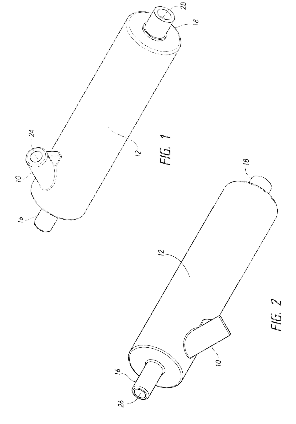
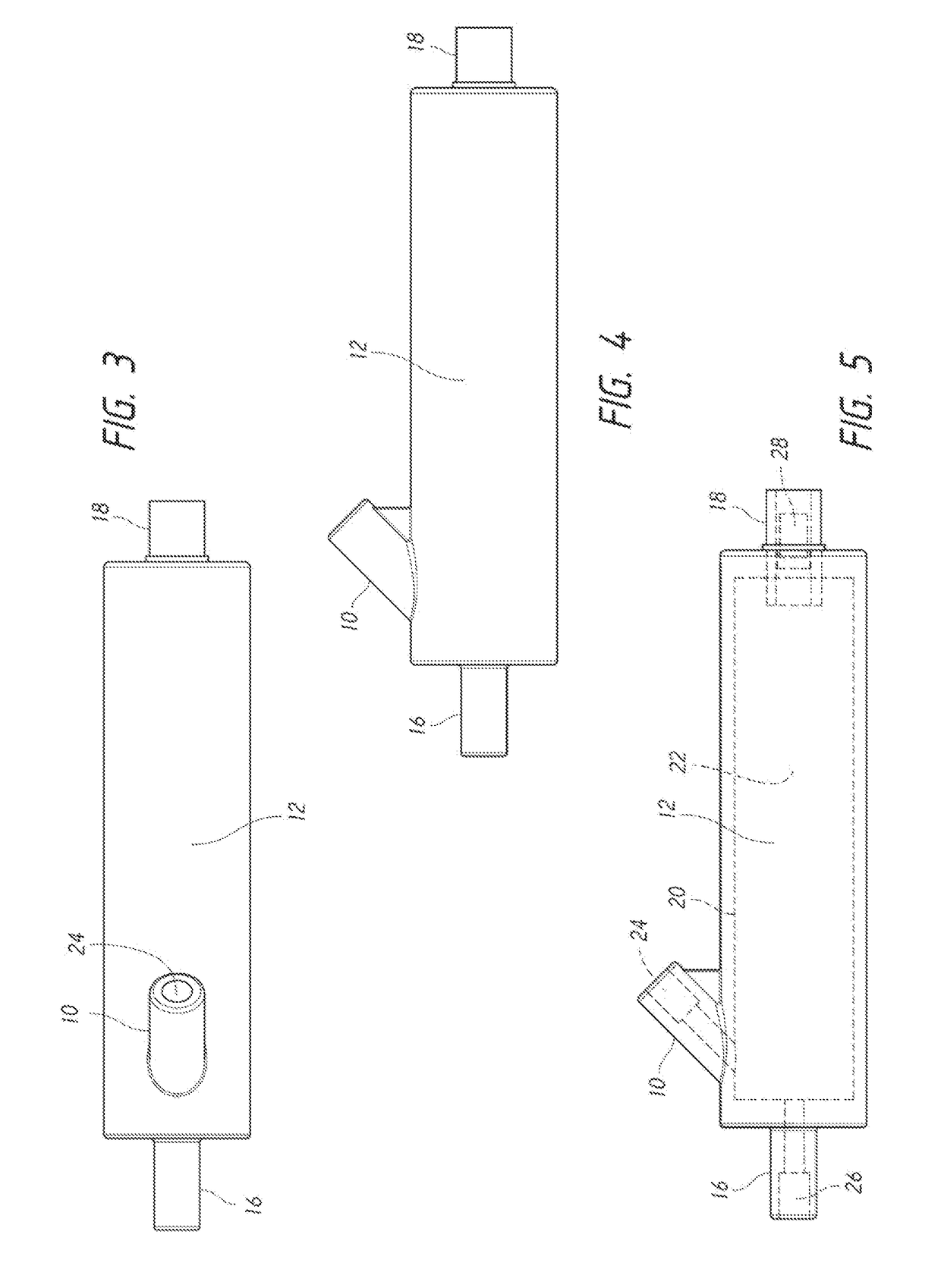
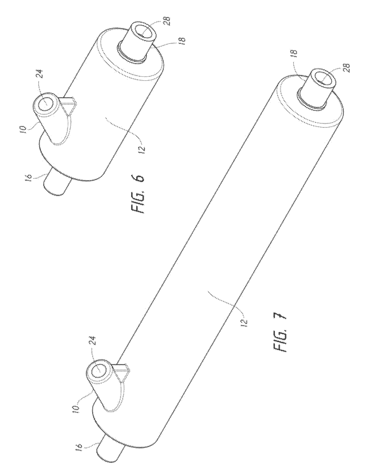
[0032]A fluid delivery system is to include an air removal device (e.g., air catch, degasser, etc.). The fluid delivery system is configured to transport a fluid from a fluid source to a patient through generally closed passage, such as a passage provided by a length of tubing. In other embodiments, the fluid may be supplied from another source, such as a bottle or other closed, sterile container. The fluid delivery system may be used to deliver a variety of fluids, each containing varying levels of viscousness, to the blood vessel of a patient including, but not limited to, volume expanders (e.g., a saline solution (NaCl) as fluid replacement to fight dehydration, a glucose solution etc.), whole blood (e.g., a blood transfusion), blood components (e.g., red blood cells, plasma, platelets, etc.), or medicine (e.g., chemotherapy medicine, antibiotics, etc.)

[0033]The fluid delivery system may be coupled via an appropriate outlet connector to a catheter inserted through the skin and in...


PUM


Abstract

An apparatus having an outer wall that encompasses an interior chamber that holds a predetermined volume of fluid and gas where the gas rises to one end of the interior chamber and the fluid flows to the other end of the interior chamber. The apparatus also has an inlet port that allows for fluid to ingress into the interior chamber and an outlet port that allows for fluid to egress out of the interior chamber.

Description

CLAIM OF BENEFIT TO PRIOR APPLICATIONS[0001]This application is a continuation-in-part application of U.S. patent application Ser. No. 15 / 950,002 filed on Apr. 10, 2018, which is a continuation-in-part of U.S. patent application Ser. No. 15 / 116,998 filed on Aug. 5, 2016, now published as U.S. Patent Publication 20170165435A1, which is a national filing of PCT / US2014 / 016595 filed on Feb. 14, 2014, all of which are incorporated herein by reference in their entirety.FIELD OF THE DISCLOSURE[0002]The present disclosure is related generally to the field of fluid delivery apparatuses and more particularly to apparatuses for removing unwanted gas (e.g., air) from a fluid, apparatus or device in a variety of industries and environments.GENERAL BACKGROUND[0003]Gas found in lines, such as intravenous fluid lines, hydraulic lines, water lines or pipes, or car fluid systems such as oil and brakes, often times forms air pockets which can be detrimental to the instrument or process. In the medical...

Claims


Application Information

Patent Timeline
Patent Type & Authority Applications(United States)
IPC IPC(8): A61M5/36A61M5/168
CPCA61M5/36A61M5/16822A61M5/16813A61M2205/18A61M2205/581A61M5/1411A61M5/16877A61M2005/1403A61M5/16831
Inventor HERRICK, NORTONSALOFF, DAVIDGREEN, RICHARD
Owner AILNH LLC
Why Eureka
Try Eureka