Pin dismounting device used when stator part sleeve of turbine is repaired
A steam turbine and pin technology, which is applied in the field of pin removal devices when repairing the stator casing of a steam turbine, can solve the problems such as difficulty in taking out the positioning pins normally, high transportation and repair costs of machine tools, affecting the production cycle of new products, and the like. The effect of low repair cost and simple operation
- Summary
- Abstract
- Description
- Claims
- Application Information
AI Technical Summary
Problems solved by technology
Method used
Image

Examples
specific Embodiment approach 1
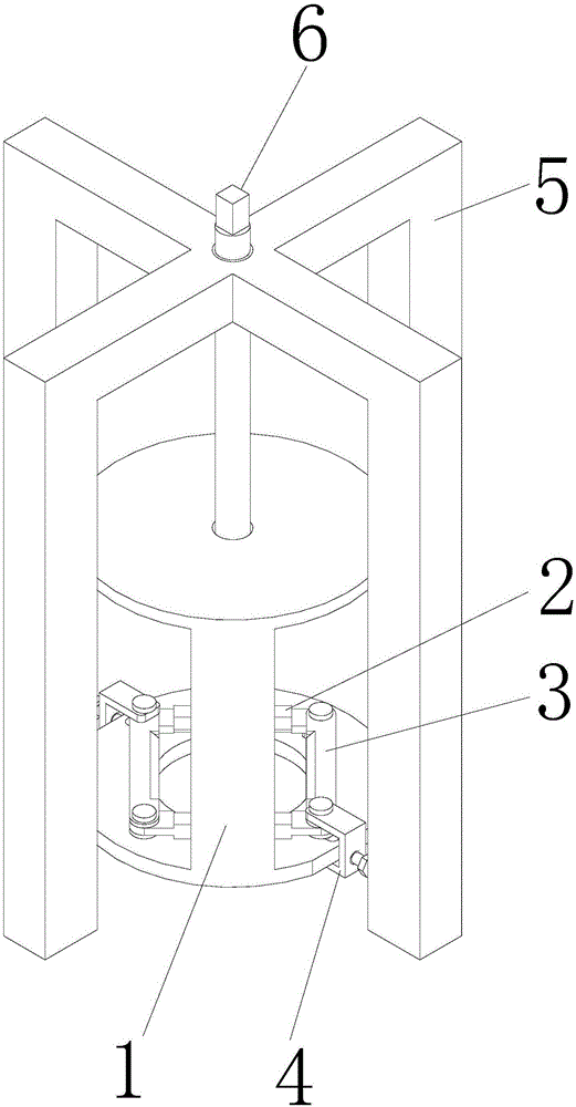
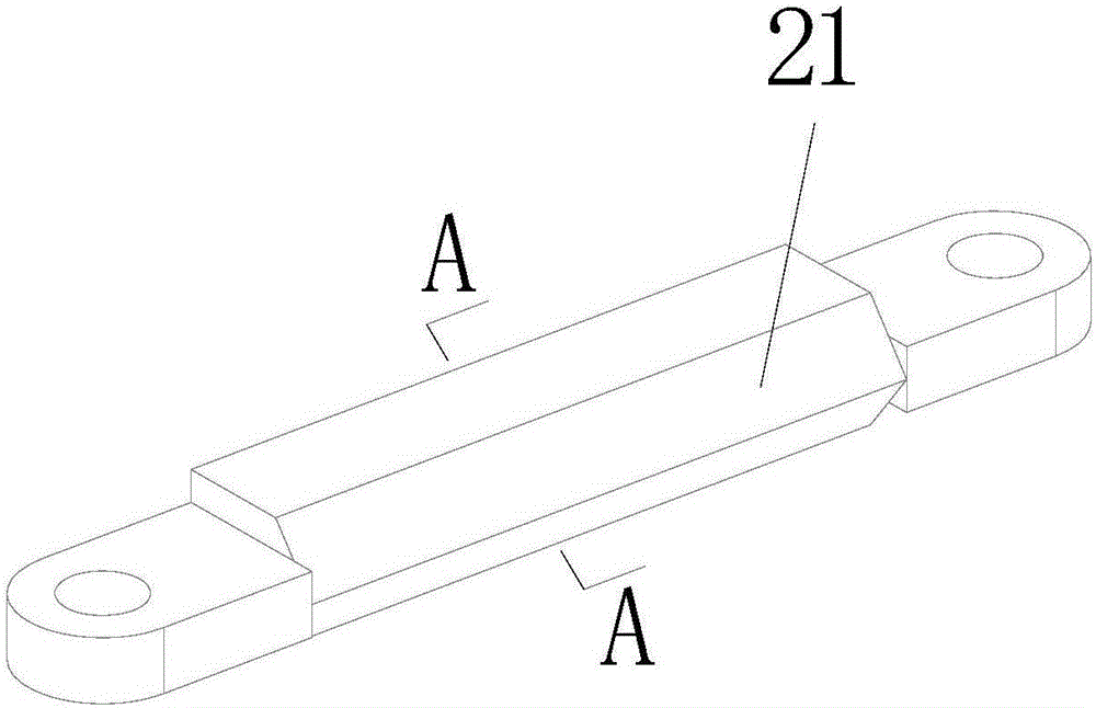
[0034] Specific implementation mode one: combine Figure 1-9 Describe this embodiment, the device for removing pins during the repair of the steam turbine stator casing in this embodiment, the device consists of a cylindrical shell 1, two first connecting rods 2, two second connecting rods 3, two U-shaped frames 4, a bracket 5 and screw rod 6 constitute;
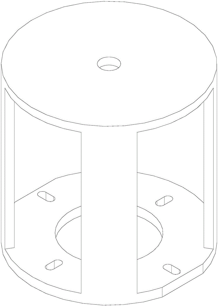
[0035] The cylindrical shell 1 is composed of a circular upper top plate, a circular lower bottom plate, and an arc-shaped connecting plate between the circular upper top plate and the circular lower bottom plate; the center of the circular upper top plate is processed with a through hole; the center of the circular lower bottom plate Through holes are processed; the edge of the circular lower base plate is processed with two symmetrical edge-cutting grooves, and the circular lower base plate is processed with four waist-shaped through holes. radii parallel to each other; two of the four waist-shaped through-holes are set a...
specific Embodiment approach 2
[0050] Embodiment 2: This embodiment differs from Embodiment 1 in that: the pin is made of high-speed steel. Other steps and parameters are the same as those in the first embodiment.
specific Embodiment approach 3
[0051] Embodiment 3: This embodiment differs from Embodiment 1 or Embodiment 2 in that: the material of the first connecting rod 2 is high speed steel. Other steps and parameters are the same as those in Embodiment 1 or 2.
PUM
 Abstract
Description
Claims
Application Information