
Underground antiwear tool performance detection method

A detection method and tool technology, applied in the direction of testing wear resistance, etc., can solve the problems of easy failure of the sealing device, lack of contrast, inaccurate friction, etc., and achieve the effects of accurate and reliable simulation, obvious comparison and evaluation, and simple operation.

Inactive Publication Date: 2017-06-09
PETROCHINA CO LTD
View PDF5 Cites 0 Cited by
  • Summary
  • Abstract
  • Description
  • Claims
  • Application Information

AI Technical Summary

Problems solved by technology

[0004] However, the above-mentioned device can only test one set of pipe and rod combinations at one time during the test, and it cannot realize the comparative test of two sets of test pieces under the same test conditions, which is not comparable; at the same time, the actual stress of the pipe and rod in the highly deviated well It is not equivalent to the test loading of the above-mentioned device on the sucker rod. For example, after the centralizer is installed on the sucker rod, the position of the centralizer directly affects the force on the sucker rod. The friction force simulated by the above-mentioned device is not accurate, and after the pipe rod is worn, The seal of the sealing device is prone to failure; therefore, it is necessary to propose a performance testing method for downhole anti-wear tools to truly simulate the friction conditions of downhole anti-wear tools and accurately evaluate the anti-wear performance of anti-wear tools

Method used


Image

  • Underground antiwear tool performance detection method
  • Underground antiwear tool performance detection method
  • Underground antiwear tool performance detection method

Examples


Embodiment Construction

[0028] The following will clearly and completely describe the technical solutions in the embodiments of the present invention with reference to the accompanying drawings in the embodiments of the present invention. Obviously, the described embodiments are only some, not all, embodiments of the present invention. Based on the embodiments of the present invention, all other embodiments obtained by persons of ordinary skill in the art without making creative efforts belong to the protection scope of the present invention.

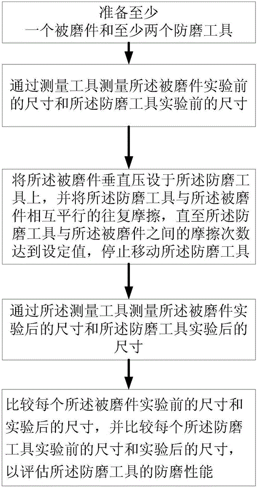
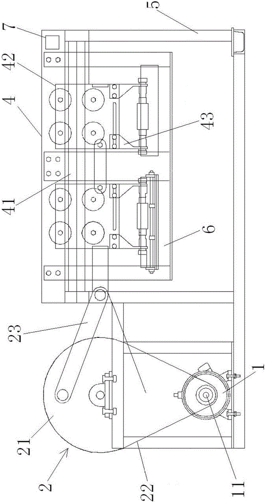
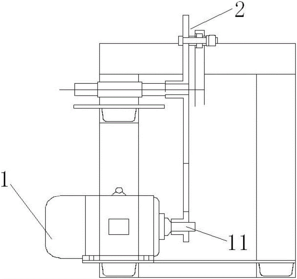
[0029] Such as Figure 1 to Figure 4 As shown, the present invention provides a method for testing the performance of downhole anti-wear tools, which includes the following steps: step S1, preparing at least one worn part and at least two anti-wear tools; step S2, measuring the worn part through a measuring tool The size before the experiment and the size of the anti-wear tool before the experiment; step S3, vertically press the wear-resistant tool on the wear...


PUM

PropertyMeasurementUnit
diameteraaaaaaaaaa

Abstract

The invention provides an underground antiwear tool performance detection method, which comprises the following steps: S1, preparing at least one piece to be worn and at least two antiwear tools; S2, measuring the pre-experiment size of the piece to be worn and the pretest size of the antiwear tools through a measuring tool; S3, pressing the piece to be worn on the antiwear tools perpendicularly, leading the antiwear tools and the piece to be worn, which are parallel to each other, to do reciprocating friction until the friction times of the antiwear tools and the piece to be worn reach a set value, and stopping the motion of the antiwear tools; S4, measuring the post-experiment size of the piece to be worn and the post-experiment size of the antiwear tools through the measuring tool; and S5, comparing the pre-experiment size with the post-experiment size of each piece to be worn, and comparing the pre-experiment size with the post-experiment size of each antiwear tool, so as to evaluate the antiwear performance of the antiwear tools. By using the underground antiwear tool performance detection method, the antiwear performance of the underground antiwear tools can be accurately evaluated, the simulation is accurate and reliable, and the realization is easy.

Description

technical field [0001] The invention relates to the technical field of petroleum exploitation, in particular to a detection method, more specifically to a performance detection method of an anti-wear tool in a downhole. Background technique [0002] At present, the eccentric wear of pipe and rod in oil and water wells is a common phenomenon in the production of pumping wells in oilfields. In large-reach directional wells and horizontal wells, the wear of pipe and rod is particularly serious due to the well structure. Every year, a large number of oil pumping is caused by the wear of pipe and rod. Accidents that affect production, such as rod breakage, tubing wear and leakage, and iron filings stuck in the pump, not only increase the operating cost and production cost, but also shorten the production efficiency of the oil well and affect the normal production of the oil field. In response to this problem, there are many kinds of anti-wear tools on the market, but the performa...

Claims


Application Information

Patent Timeline
Patent Type & Authority Applications(China)
IPC IPC(8): G01N3/56
CPCG01N3/56
Inventor 李峰徐爽周广安黄武鸣周月慧郭佳玮刘畅王肖磊王佳昊王宁辉宋星池王燕徐青竹韩有祥于洋
Owner PETROCHINA CO LTD
Learn More