
Two-input and two-output networked decoupling control system large network time delay IMC method

A technology of decoupling control and output network, applied in the field of multi-input multi-output network decoupling control system, can solve the problems of complex internal structure, difficulty in implementing delay compensation and control, and difficulty in analysis and design of control system.

Inactive Publication Date: 2017-06-09
HAINAN UNIVERSITY
View PDF0 Cites 1 Cited by
  • Summary
  • Abstract
  • Description
  • Claims
  • Application Information

AI Technical Summary

Problems solved by technology

[0011] (2) The internal structure is much more complex than SISO-NCS
[0012] (3) There may be uncertain factors in the accused
[0013] In MIMO-NDCS, there are many parameters involved, and there are many connections between control loops, and the influence of parameter changes on the overall control effect will become very complicated.
[0014] (4) Failure of control components
Time delay leads to system performance degradation and even system instability, and also brings difficulties to the analysis and design of the control system
[0020] (3) It is unrealistic to fully synchronize the clock signals of all nodes in different distribution locations in MIMO-NDCS
[0021] (4) Since in MIMO-NCS, the input and output influence each other and there is a coupling effect, the internal structure of MIMO-NDCS is more complicated than that of MIMO-NCS and SISO-NCS, and there may be more uncertain factors. It is much more difficult to implement delay compensation and control than MIMO-NCS and SISO-NCS

Method used


Image

  • Two-input and two-output networked decoupling control system large network time delay IMC method
  • Two-input and two-output networked decoupling control system large network time delay IMC method
  • Two-input and two-output networked decoupling control system large network time delay IMC method

Examples


Embodiment Construction

[0142] The following will refer to the attached Figure 5 Exemplary embodiments of the present invention will be described in detail to make the above-mentioned features and advantages of the present invention more apparent to those skilled in the art.

[0143] The specific implementation steps are as follows:

[0144] For closed loop control loop 1:

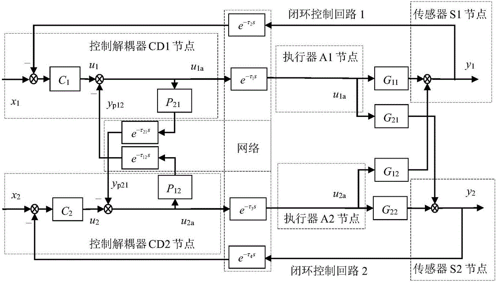
[0145] Step 1: The sensor S1 node works in the time-driven mode, and is cycled as h 1 After the sampling signal of is triggered, the controlled object G 11 (s) output signal y 11 (s) and the controlled object cross-channel transfer function G 12 (s) output signal y 12 (s), and the output signal y of the A1 node of the actuator 11mb (s) Sampling and calculating the system output signal y of the closed-loop control loop 1 1 (s) and the feedback signal y 1b (s), and y 1 (s)=y 11 (s)+y 12 (s) and y 1b (s)=y 1 (s)-y 11mb (s);

[0146] Step 2: The sensor S1 node will feed back the signal y 1b (s), through the feedback ...


PUM


Abstract

The invention discloses a two-input and two-output networked decoupling control system large network time delay IMC method, and belongs to the MIMO-NDCS technology field having limited bandwidth resources. By aiming at influences and coupling between two-input and two-output signals, decoupling processing of TITO-NDCS is required, and because of the network time delay generated by transmission of network data among nodes, stabilities of various closed-loop control circuits are affected, and stability of a whole system is affected, and then the problem of the loss of the stability of the TITO-NDCS can be even caused. The method of using the process of the network data transmission among all of the actual nodes of the TITO-NDCS to replace a network time delay compensation model is provided, and two-freedom degree IMC and one-freedom degree are carried out on the two closed loop control circuits, and therefore the measurement, the estimation, or the identification of the network time delay among the nodes are eliminated, a requirement on synchronization of node clock signals is lowered, the influences of the network time delay on the stability of the TITO-NDCS are reduced, and system control performance quality is improved.

Description

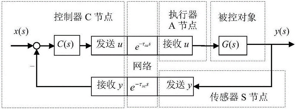
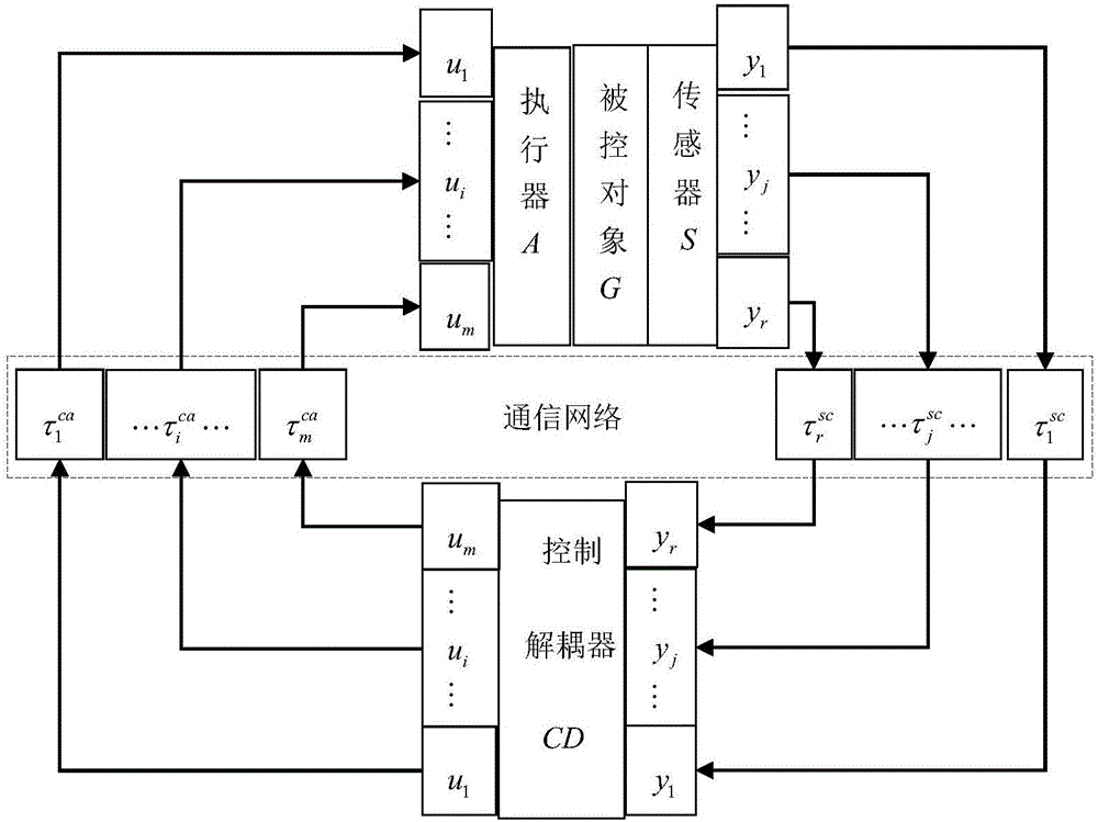
technical field [0001] An IMC (Internal Model Control, IMC) method for a large network delay in a two-input and two-output network decoupling control system, which involves the intersection of automatic control technology, network communication technology and computer technology, especially involving multiple input and multiple output with limited bandwidth resources The technical field of network decoupling control system. Background technique [0002] A closed-loop feedback control system composed of a real-time communication network is called a networked control system (Networked control systems, NCS). NCS is a distributed control system integrating communication network and control system. It also has the functions of signal processing, optimal decision-making and control operation. The typical structure of NCS is as follows: figure 1 shown. [0003] Compared with the traditional point-to-point direct control system, the biggest feature of NCS is that the sensors, cont...

Claims


Application Information

Patent Timeline
IPC IPC(8): G05B13/04
CPCG05B13/042
Inventor 杜锋
Owner HAINAN UNIVERSITY
Learn More