A Distribution Transformer Simulating Winding Short Circuit State

A technology for short-circuiting of distribution transformers and windings, applied in transformers, variable transformers, transformer/inductor components, etc., can solve the problems of limited inter-turn winding short-circuit status, limited number of lead bushings, and inability to simulate short-circuit status, etc. Achieve the effect of improving accuracy and precise short-circuit status

Active Publication Date: 2018-06-29
YUNNAN POWER GRID CO LTD ELECTRIC POWER RES INST
View PDF4 Cites 0 Cited by
  • Summary
  • Abstract
  • Description
  • Claims
  • Application Information

AI Technical Summary

Problems solved by technology

[0005] However, in the existing experimental devices, the first device is to apply a large current to the transformer winding from the outside by setting the input and output terminals of the short-circuit current, which can only simulate the state of the entire winding being short-circuited, and cannot simulate the specific conditions in the winding. The specific inter-turn short circuit state between the wire layers and in a certain wire layer of the winding, the simulation of the short circuit state of the distribution transformer winding is not accurate enough, and it is impossible to provide specific guidance for the structural improvement of the distribution transformer
The second device short-circuits different inter-turn windings of the same wire layer through wires, which can simulate the short-circuit state of different inter-turn windings, but cannot simulate the short-circuit state between different wire layers in the winding; and this device has a limited number of lead sleeves , the short-circuit state of inter-turn windings that can be simulated is limited, which makes the experimental method not flexible enough

Method used


Image

  • A Distribution Transformer Simulating Winding Short Circuit State
  • A Distribution Transformer Simulating Winding Short Circuit State
  • A Distribution Transformer Simulating Winding Short Circuit State

Examples


Embodiment Construction

[0029] The exemplary embodiments will be described in detail here, and examples thereof are shown in the accompanying drawings. When the following description refers to the accompanying drawings, unless otherwise indicated, the same numbers in different drawings represent the same or similar elements. The implementation manners described in the following exemplary embodiments do not represent all implementation manners consistent with the present invention. Rather, they are merely examples of devices and methods consistent with some aspects of the present invention as detailed in the appended claims.

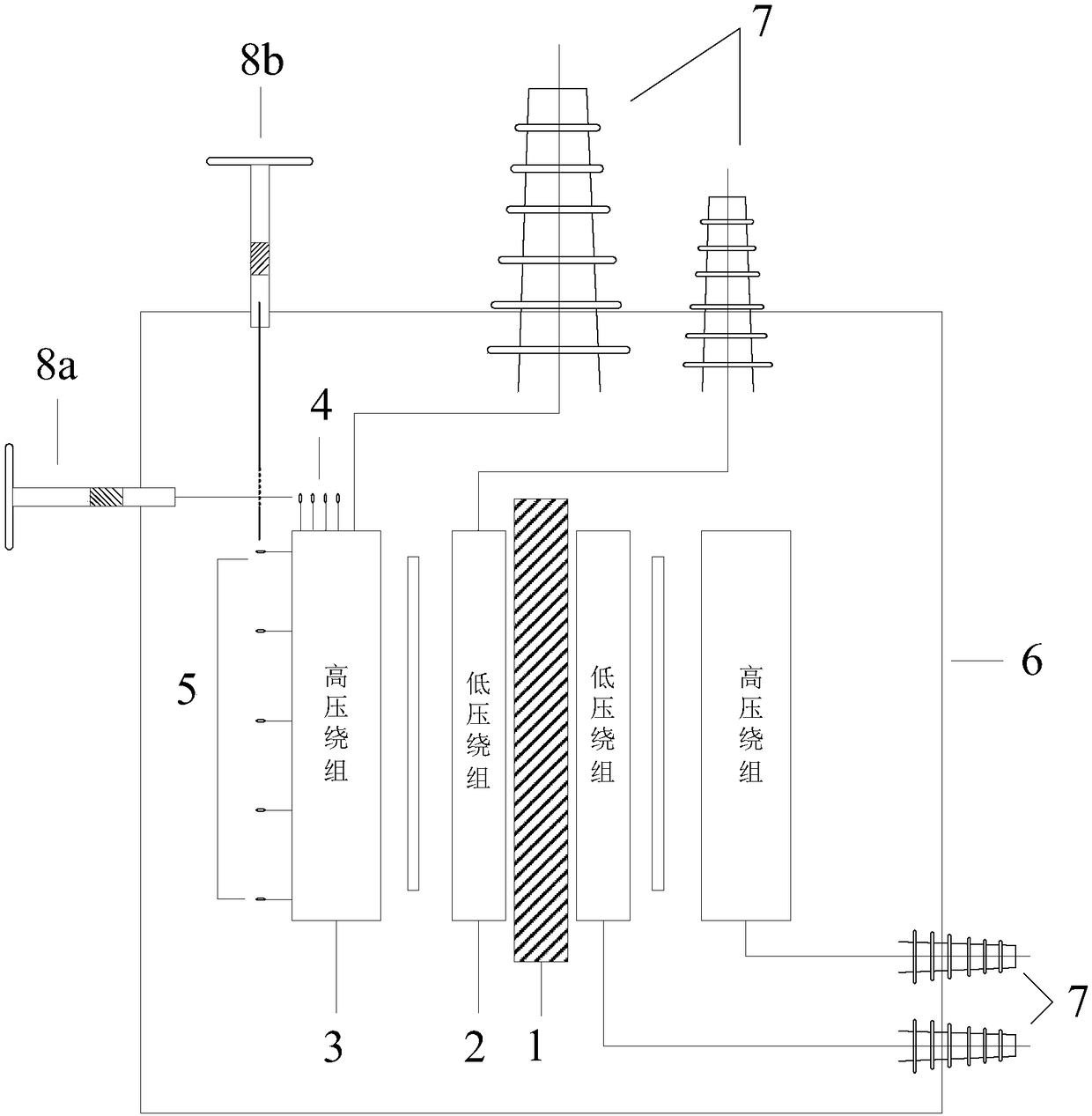
[0030] Distribution transformers are power transformers that run in the distribution network with a voltage level of 10-35KV and a capacity of 6300KVA and below that directly supply power to end users. They can transform the high voltage in the high voltage grid into a low voltage suitable for industrial and daily use. . Generally, a distribution transformer is composed of an iro...


PUM


Abstract

The invention discloses a distribution transformer for simulating a short circuit state of a winding. The distribution transformer comprises an iron core, a low-voltage winding and a high-voltage winding, wherein the low-voltage winding and the high-voltage winding are sequentially arranged on the iron core from inside to outside; a plurality of winding interlayer taps are arranged on different wire layers of the high-voltage winding; a plurality of winding inter-turn taps are arranged on different winding turns of a same wire layer; a shell is arranged outside the iron core, the low-voltage winding and the high-voltage winding; four lead casings are fixedly arranged on the shell; leads of the low-voltage winding and the high-voltage winding are led out of the shell via corresponding lead bushings respectively; a first spiral ranging conductive rod and a second spiral ranging conductive rod corresponding to the winding interlayer taps and the winding inter-turn taps respectively are fixedly arranged on the shell. By adopting the distribution transformer, short connection parts of the winding interlayer taps and the winding inter-turn taps can be precisely controlled, and in addition, the lengths of the conductive rods can be changed; the distribution transformer is simple in structure, flexible to operate, high in accuracy of simulation experiment results, and applicable to popularization and application.

Description

Technical field [0001] The present invention relates to the technical field of power system experimental devices, in particular to a distribution transformer that simulates the short-circuit state of windings. Background technique [0002] Distribution transformers are power transformers that run in the distribution network with a voltage level of 10-35KV and a capacity of 6300KVA and below that directly supply power to end users. The secondary voltage of the distribution transformer is about 400V. Generally, it is composed of high-voltage windings and low-voltage windings. Double winding structure composed of windings. Distribution transformers are widely used in industrial and mining enterprises, urban streets and remote villages. Due to their wide range of applications, once a failure occurs, they will bring major hidden dangers to the safe operation of the power grid, which will bring huge losses and inconveniences to industrial and agricultural production and people's lives....

Claims


Application Information

Patent Timeline
Patent Type & Authority Patents(China)
IPC IPC(8): H01F27/30H01F27/04H01F27/32H01F27/28H01F29/02G01R1/20
CPCG01R1/20H01F27/04H01F27/2876H01F27/306H01F27/324H01F29/02
Inventor 刘光祺赵毅刘轩东王科钱国超邹徳旭颜冰
Owner YUNNAN POWER GRID CO LTD ELECTRIC POWER RES INST
Why Eureka
Try Eureka