Eureka AIR delivers breakthrough ideas for toughest innovation challenges, trusted by R&D personnel around the world.

tubular fuel cell

A fuel cell and tubular technology, applied in fuel cells, fuel cell additives, fuel cell heat exchange, etc., can solve the problems of short service life, unfavorable popularization, high production cost, and achieve compact and orderly structure and reasonable heat exchange. , the effect of high thermal efficiency

Active Publication Date: 2019-06-21
FOSHAN SUOFUKE HYDROGEN ENERGY CO LTD
View PDF3 Cites 0 Cited by
  • Summary
  • Abstract
  • Description
  • Claims
  • Application Information

AI Technical Summary

Problems solved by technology

[0002] At present, the electrolyte in the lithium battery is a liquid, which will evaporate, flow and corrode the battery. The service life is short, and the lithium battery cannot generate electricity by itself. Although it can generate electricity by itself, the technical level of nuclear power generation is relatively high, and the production cost is relatively high, which is not conducive to popularization

Method used


Image

  • tubular fuel cell
  • tubular fuel cell
  • tubular fuel cell

Examples


Embodiment Construction

[0022] The specific embodiments of the present invention will be further described below in conjunction with the accompanying drawings. It should be noted here that the descriptions of these embodiments are used to help understand the present invention, but are not intended to limit the present invention. In addition, the technical features involved in the various embodiments of the present invention described below may be combined with each other as long as they do not constitute a conflict with each other.

[0023] In the description of the present invention, the orientations or positional relationships indicated by the terms "front" and "rear" are based on the orientations or positional relationships shown in the accompanying drawings, and are only for convenience and description of the present invention rather than requiring that the present invention must be based on a specific configuration and operation, and therefore should not be construed as limiting the invention. ...


PUM


Abstract

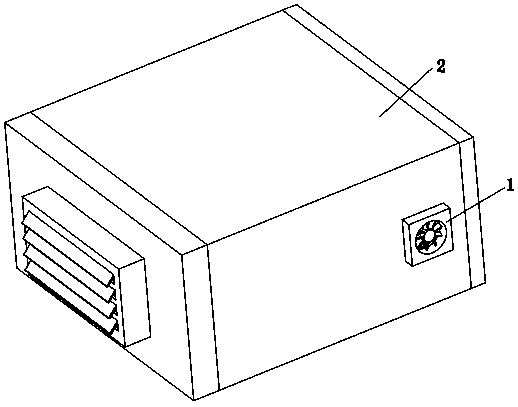
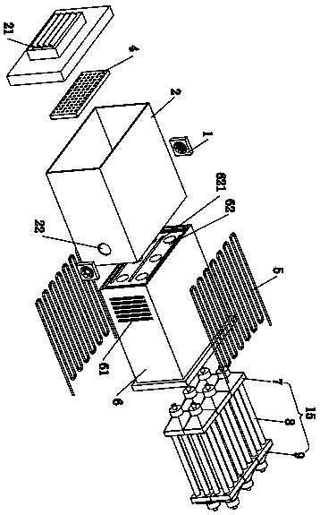
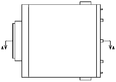
The invention relates to a tubular fuel cell which is characterized by comprising an outer shell, a thermal insulation inner shell, a first louvre damper, a second louvre damper, sub-stacks, an electric heating tube and a fan, wherein a ventilation opening and an exhaust opening are formed in the outer shell; the thermal insulation inner shell is integrally arranged in an inner cavity of the outer shell; the thermal insulation inner shell is in clearance fit with the outer shell to form an air flow channel; ventilation holes are formed in the thermal insulation inner shell; a front thermal insulation end plate and a rear thermal insulation end plate are respectively arranged at a front end part and a rear end part of the thermal insulation inner shell; a tail gas outlet is formed in the rear thermal insulation end plate; the first louvre damper and the second louvre damper are respectively arranged inside the ventilation opening and the exhaust opening; the sub-stacks are arranged in the thermal insulation inner shell and are in clearance fit with each other; the sub-stacks comprise tail gas processors, ceramic tubes and fuel gas distributors; a gas inlet tube and a gas outlet tube of each fuel gas distributor are respectively communicated with external fuel gas and a gas inlet of each ceramic tube; the gas inlet tube and the gas outlet tube of each tail gas processor are respectively communicated with the gas outlet and the exhaust opening of each ceramic tube; two adjacent ceramic tubes are in clearance fit with each other to form a cathode air flow channel; the electric heating tube heats the cathode air flow channel. The tubular fuel cell has the advantages of having high thermal efficiency, preventing outer walls of the ceramic tubes from depositing carbon, and having compact and ordered structure.

Description

technical field [0001] The invention relates to a tubular fuel cell. Background technique [0002] At present, the electrolyte in the lithium battery is a liquid, which will evaporate, flow and corrode the battery. The service life is short, and the lithium battery cannot generate electricity by itself. Although it can generate electricity by itself, the technical level of nuclear power generation is relatively high, and the production cost is relatively high, which is not conducive to popularization. Contents of the invention [0003] The purpose of the present invention is to overcome the deficiencies of the prior art and provide a tubular fuel cell. The battery constituent materials are all solid, without the evaporation, flow and corrosion of the electrolyte; the heat exchange of the tubular fuel cell is reasonable and the thermal efficiency is high; electric heating is adopted The tube heats the inside of the heat-insulated inner shell, effectively preventing carbon ...

Claims


Application Information

Patent Timeline
Patent Type & Authority Patents(China)
IPC IPC(8): H01M8/243H01M8/04007H01M8/04014H01M8/2475
CPCH01M8/04014H01M8/04037H01M8/243H01M8/2475Y02E60/50
Inventor 梁波凯文·肯德尔杨水平杨华政李斯琳
Owner FOSHAN SUOFUKE HYDROGEN ENERGY CO LTD
Why Eureka
Eureka Blog
Learn More