Mobile terminal
A mobile terminal and display module technology, which is applied in the direction of telephone structure, telephone communication, electrical components, etc., can solve problems such as poor structural stability, achieve the effects of improving connection reliability, convenient installation and operation, and improving visual effects
- Summary
- Abstract
- Description
- Claims
- Application Information
AI Technical Summary
Problems solved by technology
Method used
Image
Examples
Embodiment 1
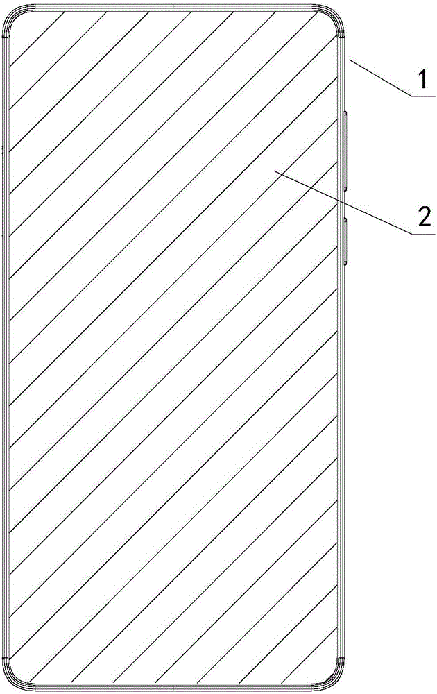
[0045] Such as figure 1 As shown, Embodiment 1 of the present invention provides a mobile terminal, including a housing 1 and a display module 2 connected to the housing 1; corresponding installation operations.
[0046] Such as figure 2 as shown, figure 2 A right side view of the above mobile terminal is shown.
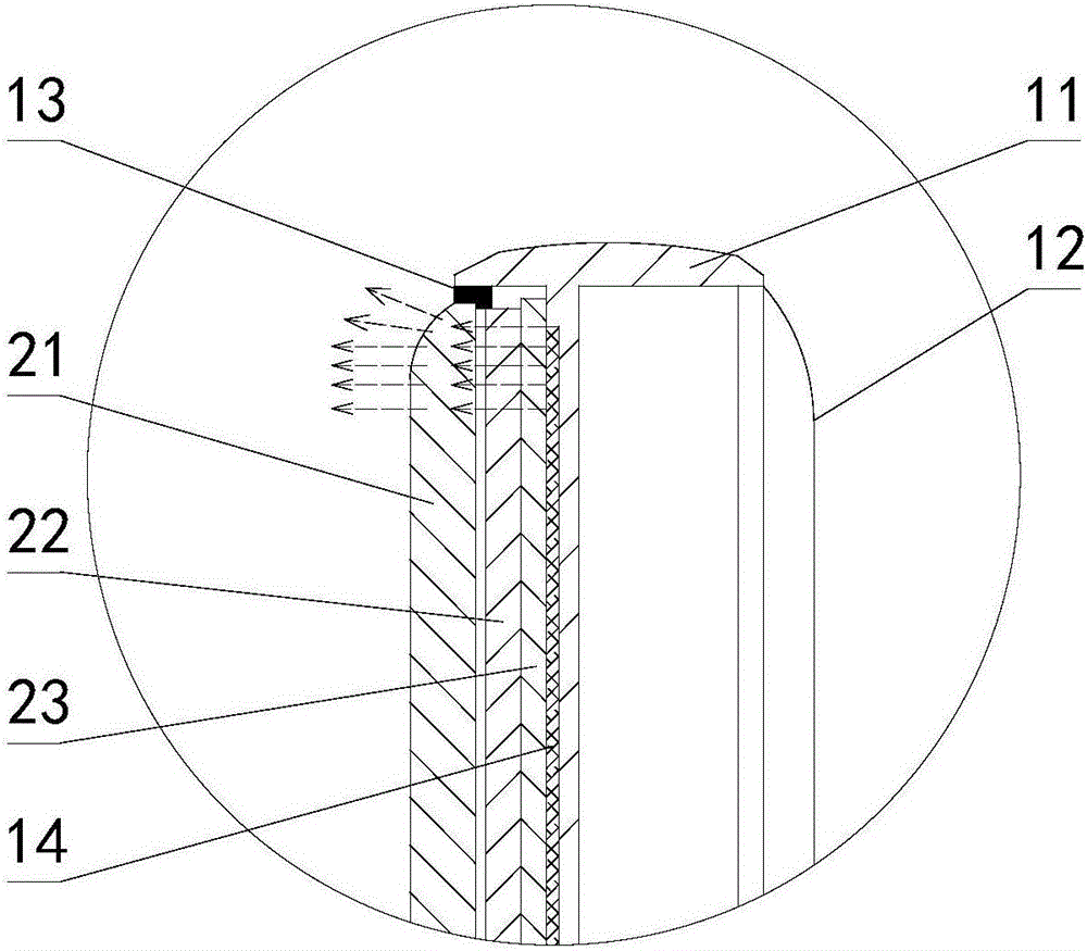
[0047] Such as image 3 As shown, the above-mentioned casing 1 provided by the present invention includes a bottom casing 12 and a middle frame casing 11. A groove is provided on one side of the middle frame casing 11, that is, a groove is provided on the front side; the other side of the middle frame casing 11 Connectors are provided, that is, connectors are provided on the back side; the above-mentioned display module 2 can be fixed in the groove by multi-point bonding, and the above-mentioned bottom case 12 can be buckled on the middle frame housing 11 through the connectors.
[0048] Compared with the prior art, the multi-point adhesive bonding between the...
Embodiment 2
[0066] The substantial difference between the second embodiment and the first embodiment is that a cover plate 3 is also provided.
[0067] The main structure in this embodiment is similar to that in Embodiment 1. For relevant records, please refer to the records in Embodiment 1. The purpose here is to explain the differences between the two.
[0068] Such as Figure 4 As shown, Embodiment 1 of the present invention provides a mobile terminal, the main structure is similar to Embodiment 1, and also includes a housing 1 and a display module 2 connected to the housing 1; different from Embodiment 1, it also includes The cover plate 3, the glass cover plate 21 has four sides, three of the four sides are connected to the side wall of the groove, and the remaining one side is connected to the side wall of the groove through the cover plate 3, and the display module The outlet area of group 2 is located inside the cover plate 3.
[0069] Such as Figure 5 as shown, Figure 5 A...
Embodiment 3
[0073] The substantial difference between the third embodiment and the first embodiment lies in that the corners of the glass cover plate 21 are arranged differently, and the display module 2 is provided with an installation cavity.
[0074] The main structure in this embodiment is similar to that in Embodiment 1. For relevant records, please refer to the records in Embodiment 1. The purpose here is to explain the differences between the two.
[0075] Such as Figure 7 As shown, in this embodiment, the corners of the above-mentioned glass cover 21 are set as rounded corners 211 , and the setting of the above-mentioned rounded corners 211 can be used to match the curvature of the shape of the middle frame housing 11 to present a better visual image.
[0076] Such as Figure 8 As shown, in this embodiment, the above-mentioned display module 2 is provided with an installation cavity, and the installation cavity can be used to install a photosensitive element, such as a camera 24...
PUM
 Abstract
Description
Claims
Application Information
 - R&D
- Intellectual Property
- Life Sciences
- Materials
- Tech Scout
- Unparalleled Data Quality
- Higher Quality Content
- 60% Fewer Hallucinations
Browse by: Latest US Patents, China's latest patents, Technical Efficacy Thesaurus, Application Domain, Technology Topic, Popular Technical Reports.
© 2025 PatSnap. All rights reserved.Legal|Privacy policy|Modern Slavery Act Transparency Statement|Sitemap|About US| Contact US: help@patsnap.com


