Deburring device applied to automobile exhaust pipes

An automobile exhaust and deburring technology, which is applied in the field of automobile exhaust pipes, can solve the problems of large removal at the pipe opening, unremoved, weak welding, etc., to achieve the effect of improving efficiency, improving effect, and ensuring the effect of deburring

Active Publication Date: 2017-06-13
浙江新诚汽车部件有限公司
View PDF8 Cites 7 Cited by
  • Summary
  • Abstract
  • Description
  • Claims
  • Application Information

AI Technical Summary

Problems solved by technology

[0002] With the development of industry, various automatic pipe cutting machines have emerged. During the cutting process, the pipe cutting machine has a downward force on the exhaust pipe, and heat will be released during the cutting process, causing the blade to burn at the nozzle during the downward pressure process. Minor radial deformation. For exhaust pipes with thinner pipe walls, the radial deformation is more serious. In the automotive industry, pipe-to-pipe connections often occur. Pipe-to-pipe connections usually insert a piece of pipe into the other end of the pipe. Welding is carried out again, and the radial deformation will cause difficulty in insertion. At the same time, welding is inconvenient and not firm during welding. In addition, after the automobile exhaust pipe is cut into standard parts by the pipe cutting machine, burrs will appear at the incision. Deburring of incisions
[0003] The traditional deburring method uses manual deburring, which is inefficient. The more advanced method is mechanical deburring. In the deburring process, two tools are usually used to deburr the inner wall and outer wall of the nozzle respectively. The radial deformation at the place will cause the phenomenon of excessive or incomplete removal

Method used


Image

  • Deburring device applied to automobile exhaust pipes
  • Deburring device applied to automobile exhaust pipes
  • Deburring device applied to automobile exhaust pipes

Examples


Embodiment 1

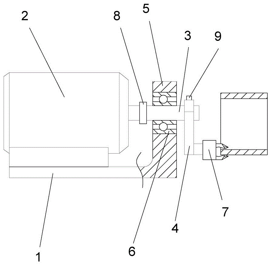
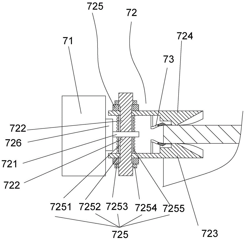
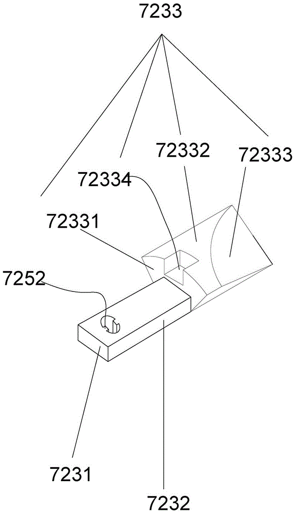
[0029] Embodiment 1: as Figure 1-5 Shown, a kind of deburring device for automobile exhaust pipe is characterized in that it comprises a mounting frame 1, a motor 2 arranged on the mounting frame 1, an output shaft 3 connected with the motor 2, and the The rotating handle 4 connected to the output shaft 3, and the deburring tool 7 connected to the rotating handle 4, which can shape the nozzle of the exhaust pipe and simultaneously deburr the outer wall and the inner wall of the exhaust pipe, the mounting frame 1 A fixed block 5 is also arranged on the top, and a bearing 6 is arranged on the output shaft 3, and the bearing 6 is located between the motor 2 and the rotating handle 4, and the bearing 6 is fixed in the fixed block 5. in the bearing mounting hole. During installation, the output shaft 3 is connected with the motor shaft through the coupling 8. This deburring device no longer adopts the method of directly using the tool to deburr in the prior art, but performs the ...

Embodiment 2

[0037] Embodiment 2: In order to improve the shaping effect, the mouth of the exhaust pipe can be properly heated to increase the deformability at the mouth of the pipe. Preferably, the device also includes a heating device, and the heating device can adopt a heat gun or an electric heating device. Heating wire. Therefore, the heating device can indirectly improve the deburring efficiency.

[0038] All the other are with embodiment 1.

Embodiment 3

[0039] Embodiment 3: A weight block 9 is fixedly arranged at the end of the rotating handle 4 away from the deburring tool 7 . The weight block 9 makes the center of mass of the turning handle 4 approach the center of rotation as much as possible, and the turning handle 4 rotates more stably. Correspondingly, the deburring cutter 7 is just more stable, and the deburring effect is just better. All the other are with embodiment 1.


PUM


Abstract

The invention discloses a deburring device applied to automobile exhaust pipes. The deburring device comprises an installation frame, a motor, an output shaft, a driving gear, an inner gear, a rotary gear and a shaping cutter, wherein the motor is arranged on the installation frame, the output shaft is connected with the motor, the driving gear is arranged on the output shaft, the inner gear is fixed to the installation frame and shares the same axis with the driving gear, the rotary gear is meshed with outer teeth of the driving gear and inner teeth of the inner gear, and the shaping cutter is coaxially connected with the rotary gear, can shape pipe openings of the exhaust pipes and can perform deburring on outer walls and inner walls of the exhaust pipes at the same time. The deburring device disclosed by the invention can shape the pipe openings of the exhaust pipes and perform deburring on the outer walls and the inner walls of the exhaust pipes at the same time, so that the pipe openings are round and neat, used time is small, and deburring efficiency is high.

Description

technical field [0001] The invention relates to the field of automobile exhaust pipes, in particular to a deburring device for automobile exhaust pipes. Background technique [0002] With the development of industry, various automatic pipe cutting machines have emerged. During the cutting process, the pipe cutting machine has a downward force on the exhaust pipe, and heat will be released during the cutting process, causing the blade to burn at the nozzle during the downward pressure process. Minor radial deformation. For exhaust pipes with thinner pipe walls, the radial deformation is more serious. In the automotive industry, pipe-to-pipe connections often occur. Pipe-to-pipe connections usually insert a piece of pipe into the other end of the pipe. Welding is carried out again, and the radial deformation will cause difficulty in insertion. At the same time, welding is inconvenient and not firm during welding. In addition, after the automobile exhaust pipe is cut into stand...

Claims


Application Information

Patent Timeline
Patent Type & Authority Applications(China)
IPC IPC(8): B23D79/04B21D3/14
CPCB21D3/14B23D79/04
Inventor 成剑峰何晓燕
Owner 浙江新诚汽车部件有限公司
Why Eureka
Try Eureka