Three-dimensional-direction pressure maintaining equipment

A three-dimensional, equipment technology, applied in the field of three-dimensional direction pressure-holding equipment, can solve the problems of complex and inapplicable pressure-holding equipment, complex structure, limited space, etc., and achieve the effect of saving equipment space, good crimping effect, and low manufacturing cost.

Active Publication Date: 2017-06-13
GEER TECH CO LTD
View PDF8 Cites 13 Cited by
  • Summary
  • Abstract
  • Description
  • Claims
  • Application Information

AI Technical Summary

Problems solved by technology

Due to the small structure and limited space of electronic and electrical products, the existing pressure-holding equipment has a complex structure and cannot be applied, and it is impossible to use drive cylinders to apply force in multiple directions for the product.
[0003] The pressurizing equipment or pressure maintaining equipment in the prior art, if you want to realize the vertical and lateral three-dimensional direction pressure, you need to set the driving mechanism in the corresponding direction, the structure is complicated, and the volume is large

Method used


Image

  • Three-dimensional-direction pressure maintaining equipment
  • Three-dimensional-direction pressure maintaining equipment
  • Three-dimensional-direction pressure maintaining equipment

Examples


Embodiment 1

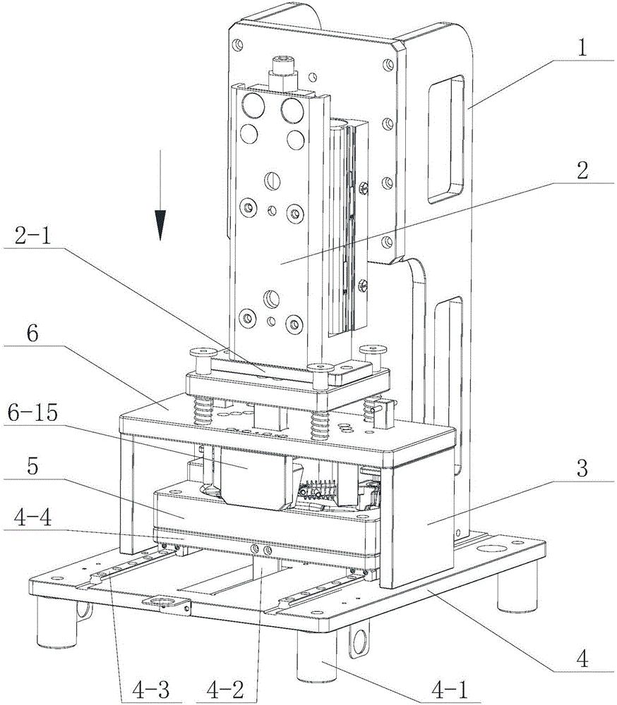
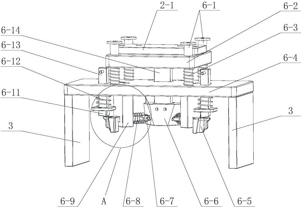
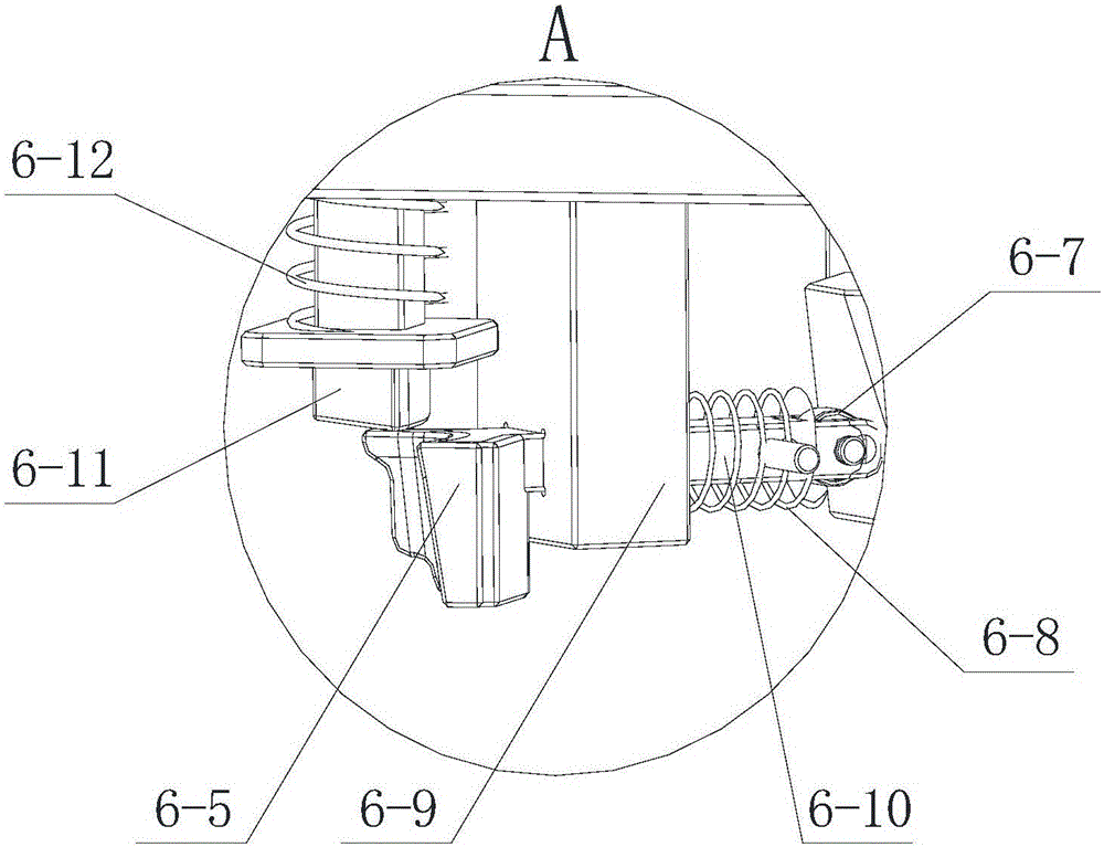
[0034] Such as figure 1 , figure 2 , Figure 4 Shown is one of the embodiments of the present invention. In this embodiment, a three-dimensional direction pressure maintaining device is provided with a frame 1, and a push-down driving mechanism 2 is arranged on the frame 1. The frame 1 is installed on a base 4 On the top, the base 4 is provided with a product placement plate 5, the product placement plate 5 is used to place the product to be kept under pressure, the pressure dividing mechanism 6 is connected to the lower part of the pressing driving mechanism 2, and the pressure dividing mechanism 6 is driven to rise and fall, and the pressure dividing mechanism 6 Several vertical pressure heads 6-11 and lateral pressure heads 6-5 are provided, and a pressure dividing block 6-6 is arranged in cooperation with the lateral pressure heads 6-5, and an inclined surface is arranged on the pressure dividing block 6-6, and the inclined surface is Downward and inclined to the inner ...

Embodiment 2

[0057] In this embodiment, the difference from Embodiment 1 is that the lateral pressure guide shafts 6-10 can move obliquely, and are inclined at a predetermined angle with respect to the horizontal plane. In order to achieve this technical purpose, the axis of the guide hole in the suspension bracket 6-9 can be inclined, that is, an inclined guide hole can be provided. Such a design can keep pressure on products with more complex shapes.

[0058] Other structures of the three-dimensional direction pressure maintaining device in this embodiment are the same as those in Embodiment 1, and will not be described again here.


PUM


Abstract

The invention discloses three-dimensional-direction pressure maintaining equipment and solves the technical problems that three-dimensional-direction pressure equipment in the prior art is complex in structure and relatively large in size. The equipment is provided with a rack; a downward-pressing driving mechanism is arranged on the rack; the rack is mounted on a base; a product accommodating plate is arranged on the base and is used for accommodating a product to be subjected to pressure maintaining; the lower side of the downward-pressing driving mechanism is connected with a partial pressure mechanism; the downward-pressing driving mechanism drives the partial pressure mechanism to rise and fall; multiple vertical pressure heads and multiple lateral pressure heads are arranged in the partial pressure mechanism; a partial pressure block matched with the lateral pressure heads is arranged; slopes are arranged on the partial pressure block; the lateral pressure heads can be driven through the slopes to extend out; and in the falling process of the partial pressure mechanism, the vertical pressure heads make contact with the product for pressing firstly, in the process that the partial pressure mechanism continues to fall, the partial pressure block begins to move downwards relative to the lateral pressure heads, the slopes of the partial pressure block drive the lateral pressure heads to extend out to make contact with the product for pressing, and thus three-dimensional-direction pressure maintaining is performed on the product.

Description

technical field [0001] The invention relates to a pressure device, in particular to a three-dimensional direction pressure maintaining device that can pressurize vertically and laterally. Background technique [0002] At present, glue dispensing has been widely used in the waterproof and fixed structures of modern products, especially in the electronics and electrical appliance manufacturing industries, and is used for the coordination and assembly of electronic devices. After the dispensing is completed, it is necessary to apply an appropriate force to stabilize the bonding part. At this stage, many products require dispensing and maintaining pressure in three-dimensional space. Due to the small structure and limited space of electronic and electrical products, the existing pressure-holding equipment has a complex structure and cannot be applied, and it is impossible to use drive cylinders to apply force in multiple directions for the product. [0003] In the pressurizing ...

Claims


Application Information

Patent Timeline
Patent Type & Authority Applications(China)
IPC IPC(8): B30B7/04B30B9/00B30B15/06
CPCB30B7/04B30B9/00B30B15/065B30B15/068
Inventor 郭光东李晓峰
Owner GEER TECH CO LTD
Why Eureka
Try Eureka