The clutch mechanism of the cutting machine and the laminating device

A technology of coating device and clutch mechanism, which is applied in the field of cutting bed, can solve the problems of unstable structure, complex mechanism, high failure rate, etc., and achieve the effect of simple structure

Active Publication Date: 2018-12-11
BULLMER ELECTROMECHANICAL TECH
View PDF6 Cites 0 Cited by
  • Summary
  • Abstract
  • Description
  • Claims
  • Application Information

AI Technical Summary

Problems solved by technology

But its mechanism is more complex, the failure rate is higher, and the structure is unstable

Method used


Image

  • The clutch mechanism of the cutting machine and the laminating device
  • The clutch mechanism of the cutting machine and the laminating device
  • The clutch mechanism of the cutting machine and the laminating device

Examples


Embodiment Construction

[0024] The following are specific embodiments of the present invention and in conjunction with the accompanying drawings, the technical solutions of the present invention are further described, but the present invention is not limited to these embodiments.

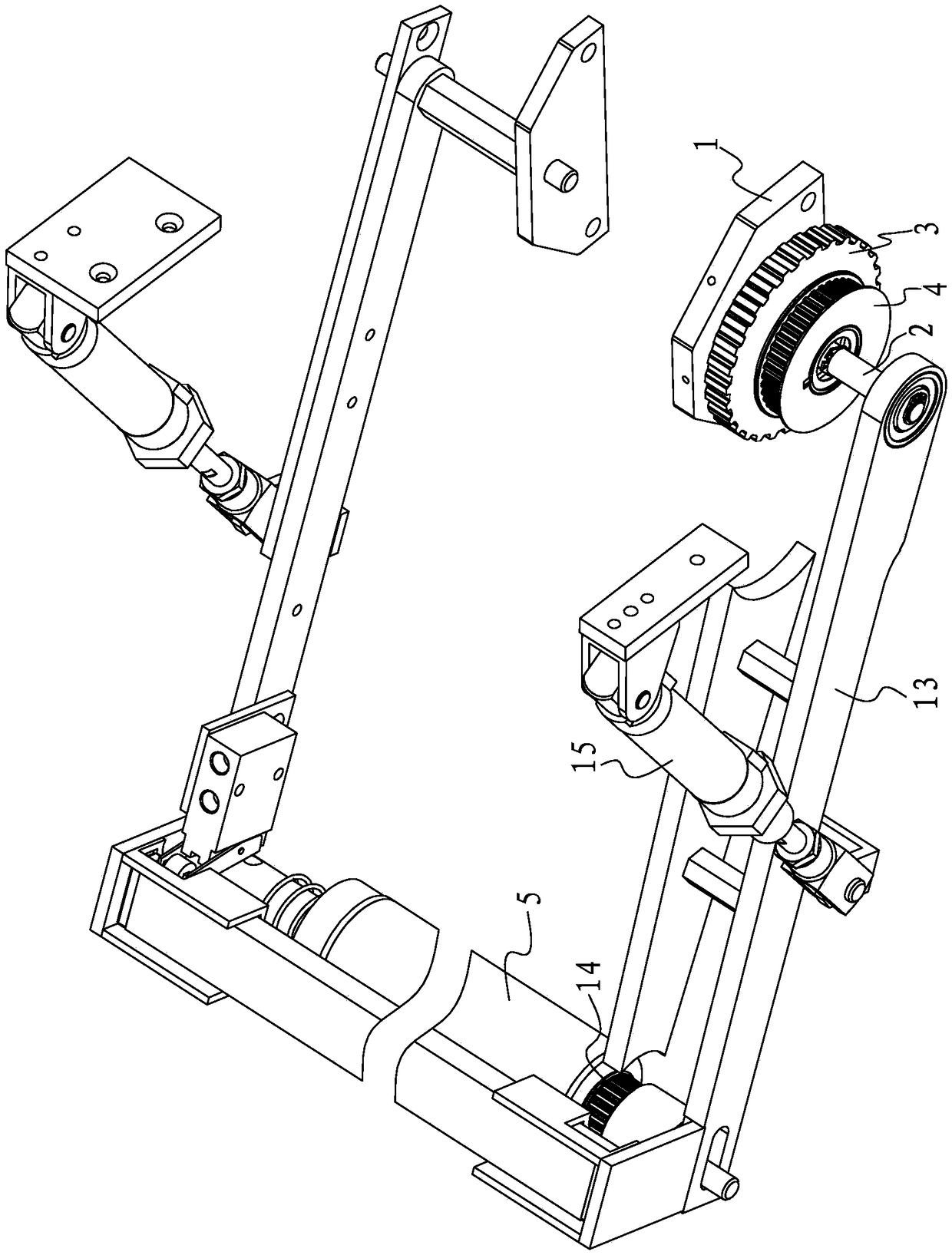
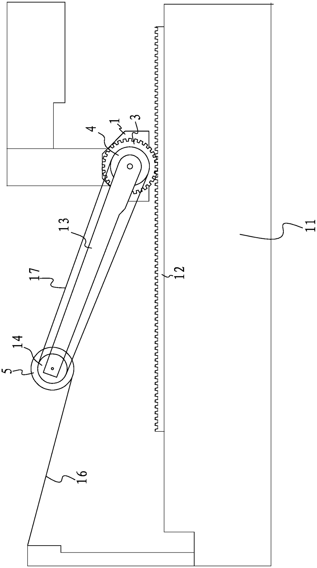
[0025] Such as figure 1 figure 2 As shown, the clutch mechanism of the cutting bed re-coating device includes a bracket 1, and a rotating shaft 2 is rotatably worn on the bracket 1, and a driving wheel 3 and a synchronous wheel-4 are sleeved on the rotating shaft 2. In addition, the rotating shaft 2 is provided with A connecting rod 13, one end of the connecting rod 13 is rotatably sleeved on the rotating shaft 2, and the other end of the connecting rod 13 is used to be connected with the coating tube 5 of the re-coating device.

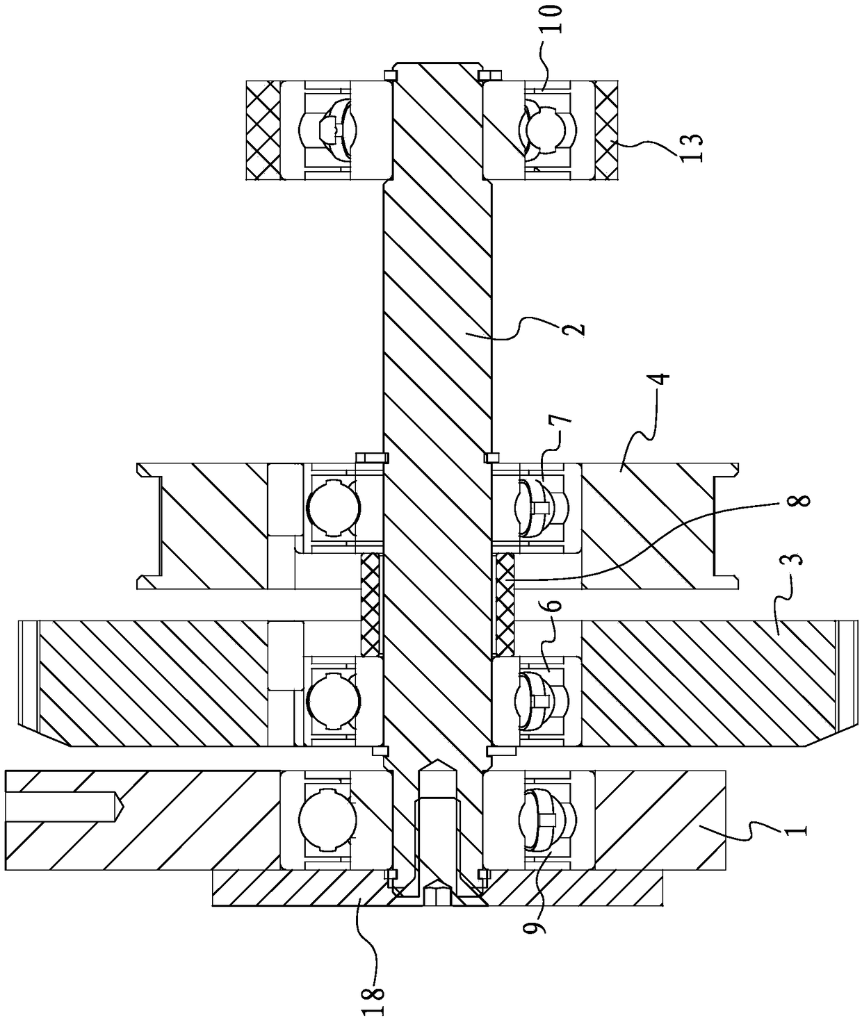
[0026] Specifically, such as figure 2 As shown, the bracket 1, the driving wheel 3, the first synchronous wheel 4 and the connecting rod 13 are sequentially arranged on the rotating shaft 2. ...


PUM


Abstract

The invention discloses a clutch mechanism of a cutting bed re-laminating device and belongs to the technical field of cutting beds. Through the mechanism, the problem that existing clutch mechanisms are complex in structure is solved. The clutch mechanism of the cutting bed re-laminating device comprises a support. A rotary shaft is rotationally arranged on the support in a penetrating mode and sleeved with a driving wheel and a first synchronous wheel. The first synchronous wheel is connected with a laminating pipe of the re-laminating device through a synchronous belt. A first unilateral bearing is arranged between the driving wheel and the rotary shaft. A second unilateral bearing is arranged between the first synchronous wheel and the rotary shaft. The first unilateral bearing and the second unilateral bearing are same in limiting direction. The structure is simple while the engaging and disengaging functions are achieved through the mechanism.

Description

technical field [0001] The invention belongs to the technical field of cutting beds, and relates to a clutch mechanism of a cutting bed re-coating device. Background technique [0002] Chinese utility model patent (authorized announcement number: CN202090214U, authorized announcement date: 20111228) discloses a re-coating device for automatic cutting bed. There is a beam above the left and right legs arranged side by side, and the beam is supported on the frame. The left side of the left leg and the right side of the right leg are respectively fixed with left and right connecting plates, the control mechanism is connected to the right connecting plate through the right cylinder connecting frame and the right coated circular shaft bracket, and the left cylinder connecting frame is connected to the left coated circular shaft bracket The hexagonal pillar is connected with the left connecting plate, and the film-coated circular shaft mechanism and square tube are arranged betwee...

Claims


Application Information

Patent Timeline
Patent Type & Authority Patents(China)
IPC IPC(8): B65H18/10B65H16/00
CPCB65H16/00B65H18/10B65H2701/1133B65H2701/1752
Inventor 彭战文周超
Owner BULLMER ELECTROMECHANICAL TECH
Why Eureka
Try Eureka