Sludge treatment device for water conservancy project

A technology for sludge treatment and water conservancy engineering, applied in sludge treatment, water/sludge/sewage treatment, dehydration/drying/thickened sludge treatment, etc., can solve problems such as poor effect and time-consuming

Active Publication Date: 2017-06-13
北京远浪潮生态建设有限公司
View PDF3 Cites 24 Cited by
  • Summary
  • Abstract
  • Description
  • Claims
  • Application Information

AI Technical Summary

Problems solved by technology

[0007] In order to overcome the disadvantages of time-consuming and poor effect of the usual sludge drying and treatment, the technical problem to be solved by the present invention is to provide not only sludge dehydration, but also compressing the sludge into a fixed Shaped sludge treatment equipment for water conservancy projects

Method used


Image

  • Sludge treatment device for water conservancy project
  • Sludge treatment device for water conservancy project
  • Sludge treatment device for water conservancy project

Examples


Embodiment 1

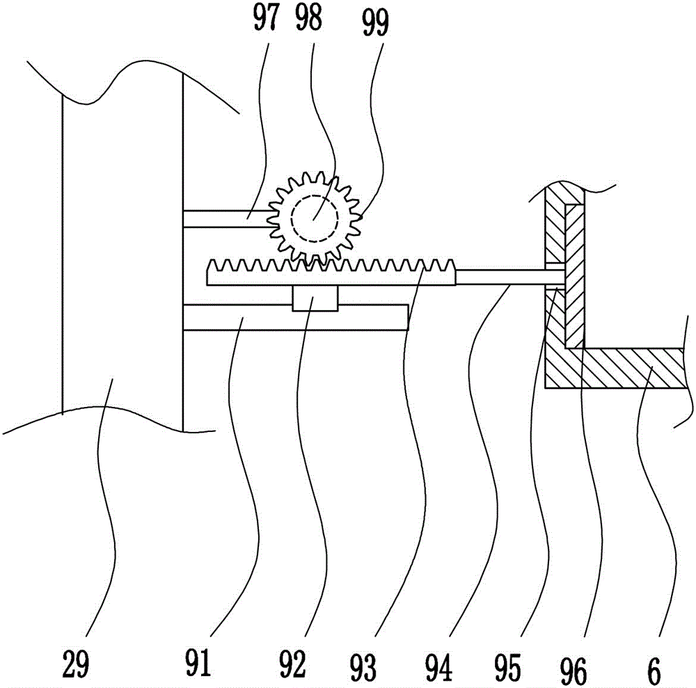
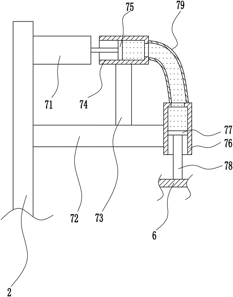
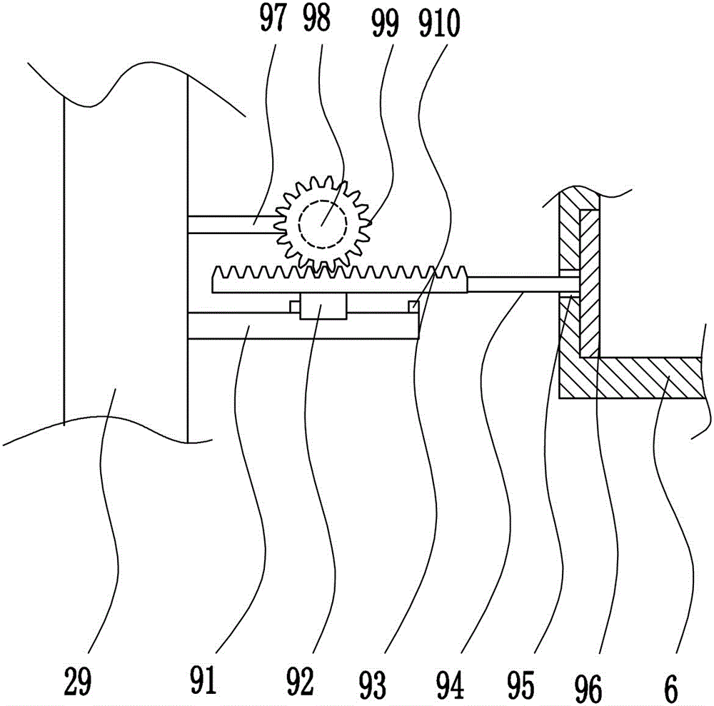
[0037] A sludge treatment equipment used in water conservancy projects, such as Figure 1-7 As shown, it includes a bottom plate 1, a mounting frame 2, a support rod 3, a collection frame 4, a processing frame 5, a pressure plate 6, a lifting mechanism 7, a feeding mechanism 8, and an ejection mechanism 9. The top of the bottom plate 1 is symmetrically provided with supports in the middle of the left and right sides. Rod 3, the top of the support rod 3 is connected with the processing frame 5, the top left end of the base plate 1 is provided with the installation frame 2, the upper part of the right side of the installation frame 2 is equipped with the lifting mechanism 7, the bottom of the lifting mechanism 7 is connected with the pressure plate 6, the pressure plate 6 and the processing frame 5 Cooperate, the lower part of the right side of the installation frame 2 is provided with an ejection mechanism 9, the ejection mechanism 9 is connected with the processing frame 5, the...

Embodiment 2

[0039] A sludge treatment equipment used in water conservancy projects, such as Figure 1-7 As shown, it includes a bottom plate 1, a mounting frame 2, a support rod 3, a collection frame 4, a processing frame 5, a pressure plate 6, a lifting mechanism 7, a feeding mechanism 8, and an ejection mechanism 9. The top of the bottom plate 1 is symmetrically provided with supports in the middle of the left and right sides. Rod 3, the top of the support rod 3 is connected with the processing frame 5, the top left end of the base plate 1 is provided with the installation frame 2, the upper part of the right side of the installation frame 2 is equipped with the lifting mechanism 7, the bottom of the lifting mechanism 7 is connected with the pressure plate 6, the pressure plate 6 and the processing frame 5 Cooperate, the lower part of the right side of the installation frame 2 is provided with an ejection mechanism 9, the ejection mechanism 9 is connected with the processing frame 5, the...

Embodiment 3

[0042] A sludge treatment equipment used in water conservancy projects, such as Figure 1-7 As shown, it includes a bottom plate 1, a mounting frame 2, a support rod 3, a collection frame 4, a processing frame 5, a pressure plate 6, a lifting mechanism 7, a feeding mechanism 8, and an ejection mechanism 9. The top of the bottom plate 1 is symmetrically provided with supports in the middle of the left and right sides. Rod 3, the top of the support rod 3 is connected with the processing frame 5, the top left end of the base plate 1 is provided with the installation frame 2, the upper part of the right side of the installation frame 2 is equipped with the lifting mechanism 7, the bottom of the lifting mechanism 7 is connected with the pressure plate 6, the pressure plate 6 and the processing frame 5 Cooperate, the lower part of the right side of the installation frame 2 is provided with an ejection mechanism 9, the ejection mechanism 9 is connected with the processing frame 5, the...


PUM


Abstract

The invention relates to a sludge treatment device, in particular to a sludge treatment device for a water conservancy project. The sludge treatment device for the water conservancy project not only can dewater sludge, but also can compress the sludge into a fixed shape. In order to solve the technical problem, the sludge treatment device for the water conservancy project comprises a bottom plate, a mounting frame, supporting rods, a collecting frame, a treatment frame, a pressing plate, a lifting mechanism and the like, wherein the supporting rods are bilaterally symmetrically arranged in the middle of the top of the bottom plate, the top ends of the supporting rods are connected with the treatment frame, the mounting frame is arranged at the left end of the top of the bottom plate, the lifting mechanism is mounted on the upper portion o the right side of the mounting frame, the bottom of the lifting mechanism is connected with the pressing plate, and the pressing plate is matched with the treatment frame. The sludge is led into the treatment frame, sewage in the sludge is squeezed out by matching the pressing plate with the treatment frame, and the squeezed sewage is discharged into a sewage treatment tank.

Description

technical field [0001] The invention relates to sludge treatment equipment, in particular to sludge treatment equipment used in water conservancy projects. Background technique [0002] Water conservancy projects are projects built to control and allocate natural surface water and groundwater to achieve the purpose of eliminating harm and rejuvenating profits. Also known as water engineering. Water is an indispensable precious resource for human production and life, but its natural state does not fully meet human needs. Only by building water conservancy projects can we control water flow, prevent floods, and regulate and distribute water to meet the needs of people's life and production for water resources. Water conservancy projects need to build different types of hydraulic structures such as dams, dikes, spillways, sluices, water inlets, channels, canals, rafts, and fishways to achieve their goals. [0003] Water conservancy projects can be divided into: flood control...

Claims


Application Information

Patent Timeline
Patent Type & Authority Applications(China)
IPC IPC(8): C02F11/12
CPCC02F11/121
Inventor 不公告发明人
Owner 北京远浪潮生态建设有限公司
Why Eureka
Try Eureka