Pile driving model test device based on soil plugging effect and application of pile driving model test device

A model test device and pile driving technology, which are applied in the test of foundation structure, construction, foundation structure engineering, etc., can solve the problems of combining soil plug and pile body, unable to simulate the dynamic response of soil around the change of soil plug, etc. Accurate testing and accurate experimental results

Inactive Publication Date: 2017-06-13
TONGJI UNIV
View PDF9 Cites 8 Cited by
  • Summary
  • Abstract
  • Description
  • Claims
  • Application Information

AI Technical Summary

Problems solved by technology

Chinese patent CN 105424913A proposes a test device for simulating the soil plugging effect in the process of sinking open pipe piles. Soil plug changes and dynamic response to surrounding soil during actual hammering pile sinking

Method used


Image

  • Pile driving model test device based on soil plugging effect and application of pile driving model test device
  • Pile driving model test device based on soil plugging effect and application of pile driving model test device
  • Pile driving model test device based on soil plugging effect and application of pile driving model test device

Examples


Embodiment 1

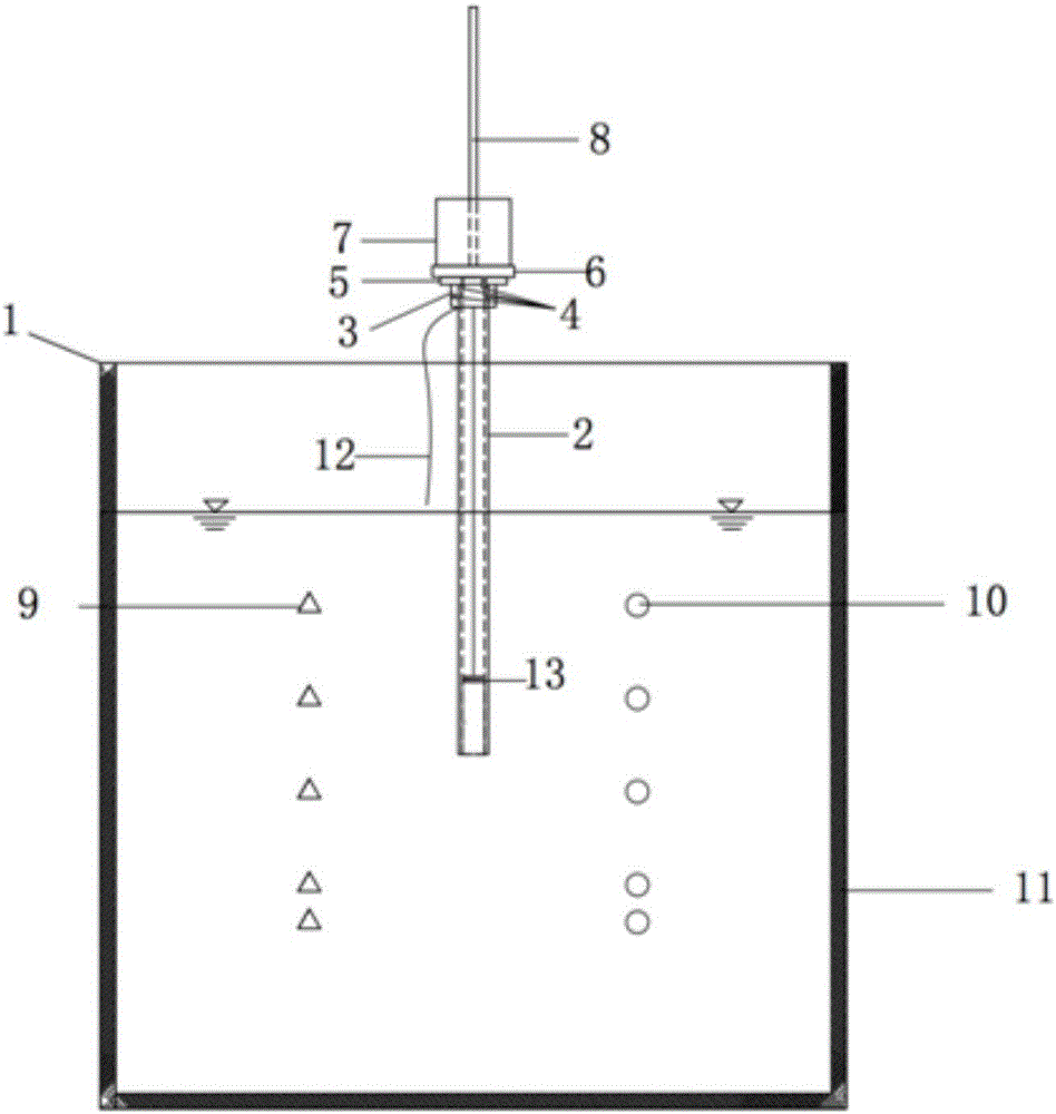
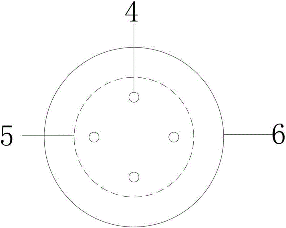
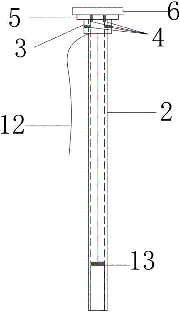
[0030] A pile sinking model test device considering the soil plugging effect, such as figure 1 As shown, it includes a model box 1, an open pipe pile 2, a guide rod 8 and a piercing hammer 7. The inside of the model box 1 is filled with a sand sample, and a miniature earth pressure gauge 10 and an acceleration sensor 9 connected to a data acquisition instrument are embedded in the sand sample. The earth pressure gauge 10 and the acceleration sensor 9 are layered in the sand sample of the model box 1, the open pipe pile 2 is vertically arranged in the center of the model box 1, and the guide rod 8 is vertically arranged at the upper end of the open pipe pile 2, and the The hammer 7 passes through the guide rod 8 and is located at the top of the open pipe pile 2. A pile cap 3 is arranged between the open pipe pile 2 and the guide rod 8. The center of the pile cap 3 is provided with a hole for inserting the guide rod 8. The upper part of the pile cap 3 Steel pad 5 is set, and rub...

Embodiment 2

[0034] The device described in Example 1 is used for the dynamic pile sinking model test of pipe piles, and the specific steps are as follows:

[0035] 1. Laying sand samples

[0036] After drying the sand sample, put it into the model box in layers using the falling rain method. The height of the falling sand is 50cm. According to the layout requirements of the instrument, the sand should reach the height where the instrument is buried, and the sand should be suspended and compacted.

[0037] 2. Buried sensors

[0038] Micro-earth pressure gauges and acceleration sensors are buried in the sand samples to explore the variation of soil pressure and acceleration at different depths during the pile sinking process. The embedding of sensors is arranged according to the most serious vibration effect of hammer piles on the surrounding soil, that is, earth pressure sensors and acceleration sensors are buried along the pile surface at distances of 1D, 3D, and 5D (D is the diameter of...


PUM


Abstract

The invention relates to a pile driving model test device based on a soil plugging effect and an application of the pile driving model test device. The pile driving model test device comprises a model box, an opening tube pile, a guide rod and a piecing hammer, wherein the model box is filled with sand samples; miniature earth pressure meters and acceleration sensors connected with a data acquisition instrument are embedded in the sand samples; the opening tube pile is vertically arranged in the center of the model box; the guide rod is vertically arranged at the upper end of the opening tube pile; the piecing hammer penetrates through the guide rod and is located at the upper part of the opening tube pile. Compared with the prior art, formation of soil plugs in a dynamic pile driving process of the tube pile can be simulated, height of the soil plugs is measured in real time, dynamic response around the pile in the dynamic pile driving process can be measured when the height of the soil plugs is fixed, boundary effect caused by model box walls is overcome, hammering power response of the opening tube pile under the soil plugging effect can be studied better, and soil compaction effect, vibration wave attenuation and load energy transmission rules caused by pile driving by the hammer are researched.

Description

technical field [0001] The invention relates to rock-soil mechanics pile foundation engineering technology, in particular to a pile sinking model test device considering the soil plugging effect and its application. Background technique [0002] While hammering pile sinking brings convenience to construction, people are increasingly concerned about its impact on the surrounding environment. The impact on the environment is generally divided into two categories, one is the soil squeezing effect, which causes uneven settlement of building foundations and underground facilities within a certain range around, causing cracking, tilting or even destruction of these buildings, road surface damage and underground Disastrous consequences such as pipeline bursting; the other is vibration damage. The vibration generated by hammering pile sinking is different from the soil vibration generated by earthquakes, and also different from the surface wave-based vibration generated by ground se...

Claims


Application Information

Patent Timeline
Patent Type & Authority Applications(China)
IPC IPC(8): E02D33/00
CPCE02D33/00
Inventor 谭勇赵冲陈万垒张宇飞
Owner TONGJI UNIV
Why Eureka
Try Eureka