Novel steel structure bracket and steel structure supporting structure
A supporting structure and steel structure technology, applied in the direction of building structure, construction, etc., can solve the problems such as the inability to set up the platform, the inability to set up the beam, and the appearance is not uniform, so as to enhance the firmness of the connection, the structure is simple, and the appearance is neat and uniform. Effect
- Summary
- Abstract
- Description
- Claims
- Application Information
AI Technical Summary
Problems solved by technology
Method used
Image

Examples
Embodiment 1
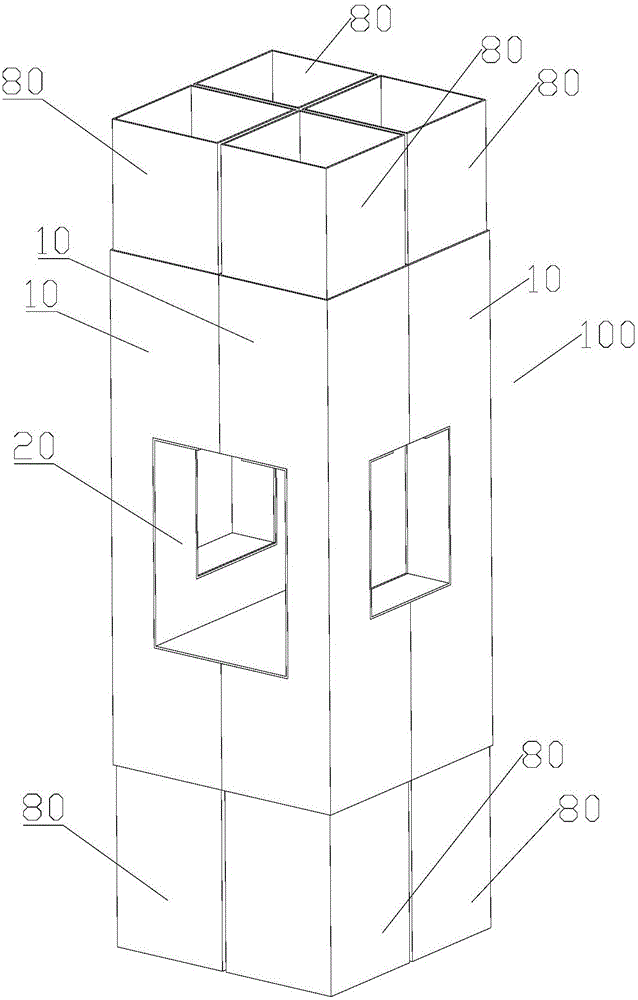
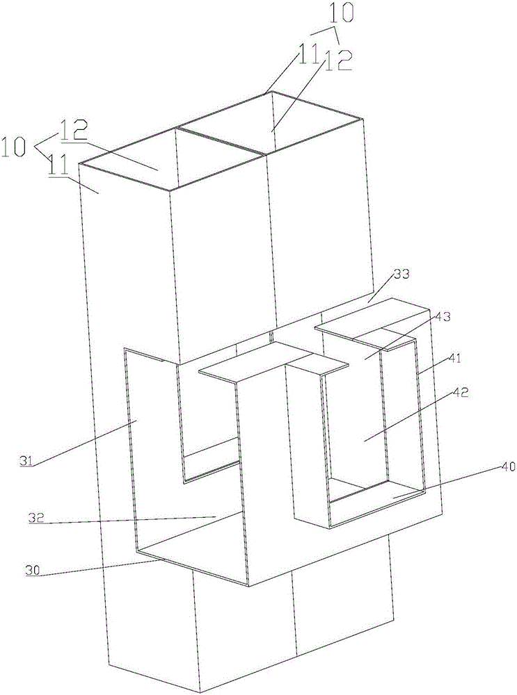
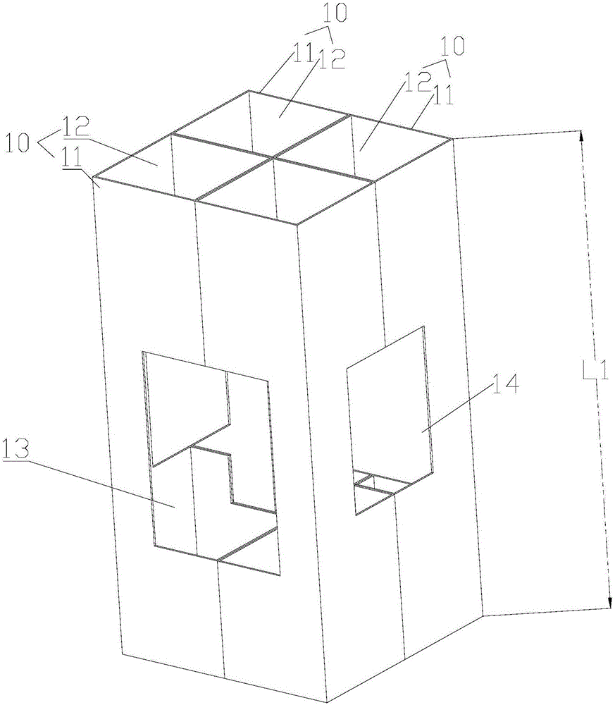
[0051] Such as figure 1 , figure 2 and image 3 As shown, the new steel structure corbel includes a casing main body 100 and a connecting piece 20 . The sleeve main body 100 is composed of more than two sleeves 10 , each sleeve 10 has a sleeve wall 11 , and the sleeve wall 11 encloses a sleeve lumen 12 . The shape of the casing wall 11 and the shape of the casing lumen 12 can be quadrangular or circular, and can also be selected as other shapes according to actual needs. The quadrilateral can be a rectangle, a square or other available shapes. In the example shown, the cannula wall 11 is rectangular and the cannula lumen 12 is also rectangular. The sleeve main body 100 is connected by four sleeves 10, and spliced into a square shape. The sleeve body 100 is provided with a first through hole 13 and a second through hole 14 . Both the first through hole 13 and the second through hole 14 are perpendicular to the length L1 direction of the sleeve body 100 , and may or may...
Embodiment 2
[0058] The difference between this embodiment and Embodiment 1 lies in that the structure of the connector 20 is different. Such as Figure 7 , Figure 8 As shown, the connector 20 is composed of a first grooved connector 50 and two second grooved connectors 60 . The first groove-type connector 50 is composed of three first connecting plates 51 , and the three first connecting plates 51 enclose a first groove 52 . The second groove-type connector 60 is composed of three second connecting plates 61 , and the three second connecting plates 61 enclose a second groove 62 . Notches 54 are defined on the two first connecting plates 51 of the first groove-type connecting member 50 . In the example shown in the figure, the number of the notches 54 is two, which are arranged opposite to each other. The two second groove-type connectors 60 are respectively welded and connected to the two first connecting plates 51 , and the second groove 62 is opposite to the notch 54 . The second ...
Embodiment 3
[0060] The difference between this embodiment and Embodiment 1 lies in that the structure of the connector 20 is different. Such as Figure 9 As shown, the connecting parts in this embodiment are two connecting plates 71 . Two connecting plates 71 are arranged at intervals along the length L1 direction of the casing main body 100 . Two connecting plates 71 are disposed in the first through hole 13 , and are respectively located on the upper wall and the lower wall of the first through hole 13 . Both connecting plates 71 are welded to the casing pipe walls 11 of the four casings 10 . A through slot 72 is disposed on the upper connecting plate 71 . The through groove 72 penetrates through the connecting plate 71 along the thickness direction of the connecting plate 71 . The through slot 71 extends along the length L3 of the connecting plate 71 .
[0061] Such as Figure 10 Shown is a schematic diagram of a steel structure support structure using the novel steel structure c...
PUM
 Abstract
Description
Claims
Application Information
 - Generate Ideas
- Intellectual Property
- Life Sciences
- Materials
- Tech Scout
- Unparalleled Data Quality
- Higher Quality Content
- 60% Fewer Hallucinations
Browse by: Latest US Patents, China's latest patents, Technical Efficacy Thesaurus, Application Domain, Technology Topic, Popular Technical Reports.
© 2025 PatSnap. All rights reserved.Legal|Privacy policy|Modern Slavery Act Transparency Statement|Sitemap|About US| Contact US: help@patsnap.com