Anti-puffing smoke exhausting device

A flue gas and smoke exhaust pipe technology, which is applied to exhaust gas devices, flue gas pipeline systems, combustion product treatment and other directions, can solve the problems of inconvenient installation and inability to prevent smoke from falling down.

Active Publication Date: 2017-06-13
阿诗丹顿燃具有限公司
View PDF10 Cites 3 Cited by
  • Summary
  • Abstract
  • Description
  • Claims
  • Application Information

AI Technical Summary

Problems solved by technology

The problem is: the installation is incon

Method used


Image

  • Anti-puffing smoke exhausting device
  • Anti-puffing smoke exhausting device
  • Anti-puffing smoke exhausting device

Examples


Embodiment Construction

[0018] The present invention will be further described below in conjunction with the accompanying drawings.

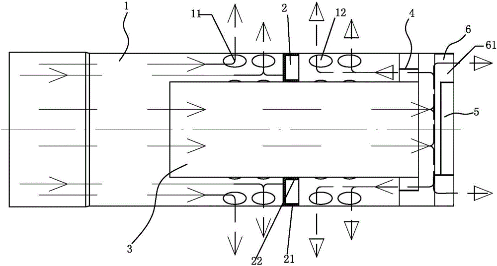
[0019] Such as figure 1 As shown, an anti-fall smoke exhaust device includes a main smoke exhaust pipe 1, a partition plate 2 with a central hole, a central pipe 3, a polygonal support 4, a top plate 5 and a top plate support 6,

[0020] The main smoke exhaust pipe 1 is provided with an inner main smoke exhaust hole 11 and an outer main smoke exhaust hole 12,

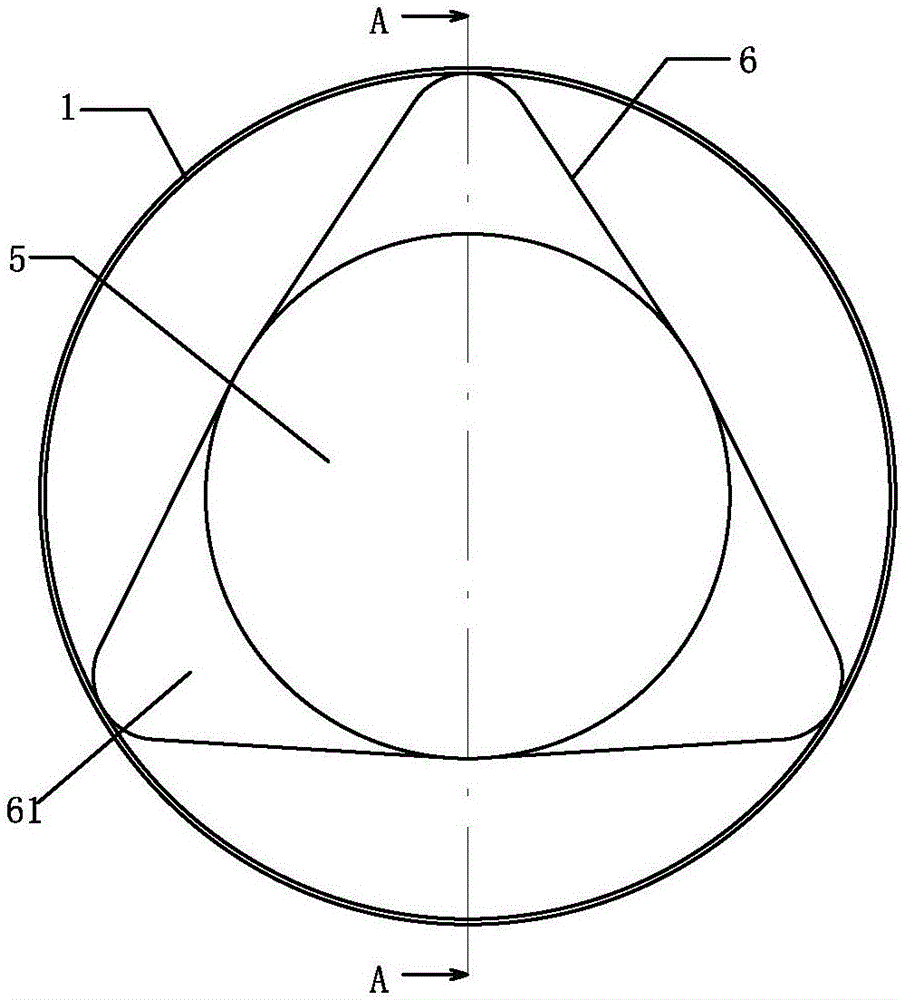
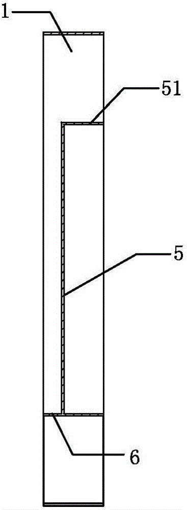
[0021] The top plate 5 is circular, and the top plate support 6 is a polygonal cylindrical shape. The top plate 5 is arranged in the top plate support 6 and inscribed with the top plate support 6 to form a top plate assembly; The space between constitutes the diversion channel 61;

[0022] One end of the central pipe 3 passes through the central hole of the partition 2 and is fixedly connected. The partition 2 is located in the middle of the central pipe 3; 11 and the main smoke exhaust pipe 1 between the out...


PUM


Abstract

The invention provides an anti-puffing smoke exhausting device. The device comprisesa main smoke exhausting pipe, apartition board with a center hole, a center pipe, atopboard and atopboard support, oneend of the center pipe passes through the center hole of the partition board and is fixedly connected, the partition board is located in the middle of the center pipe; the center pipe and the partition boardare arranged in the main smoke exhausting pipe, the partition boardis fixedly connected with the main smoke exhaust pipe betweenan inner main smoke exhaust hole and an outer main smoke exhaust hole; the top board component is arrangedin an air outlet end of the main smoke exhausting pipe, an air guide gap is arranged between the top board andthe air outlet end of the center pipe, the top board support of the top board component is connectedwith the main smoke exhaust pipe on the inner side. As a result of the adoption of such astructure, the device has a variety of smoke discharging directions, the deviceis not under the influence of wind direction, and is anti-puffing, safe and reliable, and the potential of safety risk is eliminated.

Description

technical field [0001] The invention relates to a smoke exhaust device for a gas wall hanging furnace or a gas water heater. Background technique [0002] In the current prior art, a smoke exhaust device includes a main smoke exhaust pipe and a cover body, and the diameter of the cover body is larger than that of the main smoke exhaust pipe. Existing problem is: installation is inconvenient, can't prevent smoke from falling down. Contents of the invention [0003] The purpose of the present invention is to provide an anti-dump smoke exhaust device, which has the characteristics of normal smoke exhaust and anti-dump smoke without being affected by the wind direction. [0004] The present invention is achieved in this way: an anti-fall smoke exhaust device, including the main smoke exhaust pipe, which is special in that it also includes a partition with a central hole, a central pipe, a top plate and a top plate support, [0005] The main smoke exhaust pipe is provided wit...

Claims


Application Information

Patent Timeline
IPC IPC(8): F24H9/00F23J11/00
CPCF23J11/00F23J2211/40F24H9/0005F24H9/0052
Inventor 陈秋华张吉祥
Owner 阿诗丹顿燃具有限公司
Why Eureka
Try Eureka