Automatic blowing and drying machine

A drying machine, automatic technology, applied in the direction of drying machine, drying, drying of solid materials, etc., can solve the problems of drying LED material, increase labor costs, low efficiency, etc., to improve the operation level, improve drying quality, improve work efficiency

Pending Publication Date: 2017-06-13
TANGXIA BRANCH VISION TOOL & MOLD
8 Cites 0 Cited by

AI-Extracted Technical Summary

Problems solved by technology

Due to the debris or impurities generated during the cutting process, these debris or impurities will adhere to the surface of the LED and cause damage.
Therefore, after the LED blank is cut, the LED blank will be cleaned, so there is a problem that the LED blank need...

Method used

In the present embodiment, the outlet end 32 of described transmission unit is provided with windshield 37, as shown in Figure 5, when driving belt conveys tablet to the outlet end 32 of transmission unit, prevents air knife 43 remaining from going out The wind blows the blank away. Preferably, as shown in FIG. 6 , the transmission driving mechanism 39 is provided with a sealed box 391 for protecting the driving motor from water ...

Abstract

The invention relates to equipment for automatically blowing and drying an LED (Light Emitting Diode) and particularly relates to an automatic blowing and drying machine. The automatic blowing and drying machine comprises a rack, wherein the rack is provided with a feeding unit, a conveying unit, a blowing and drying unit and a discharging unit; the feeding unit is used for carrying material pieces to be blown and dried; the conveying unit is used for conveying the material pieces; the blowing and drying unit is used for carrying out air drying on the material pieces; the discharging unit is used for carrying blown and dried material pieces; the feeding unit is arranged at one side of the inlet end of the conveying unit; the discharging unit is arranged at one side of the outlet end of the conveying unit; the blowing and drying unit is arranged at the upper part of the conveying unit; and the outer sides of the blowing and drying unit and the conveying unit are provided with shells. The automatic blowing and drying machine disclosed by the invention has the advantages that automatic conveying of the material pieces can be realized, so that the automatic operation level is improved; a relatively dry environment is formed by the shells, so that convenience is brought for fast blowing and drying; and an air knife is adopted for carrying out blowing and drying operations on the material pieces, so that multi-angle, automatic and uniform blowing and drying operations can be carried out on the material pieces, and the working efficiency and the blowing and drying quality can be improved.

Application Domain

Technology Topic

Image

  • Automatic blowing and drying machine
  • Automatic blowing and drying machine
  • Automatic blowing and drying machine

Examples

  • Experimental program(1)

Example Embodiment

[0026] The present invention will be further described in conjunction with the following examples.
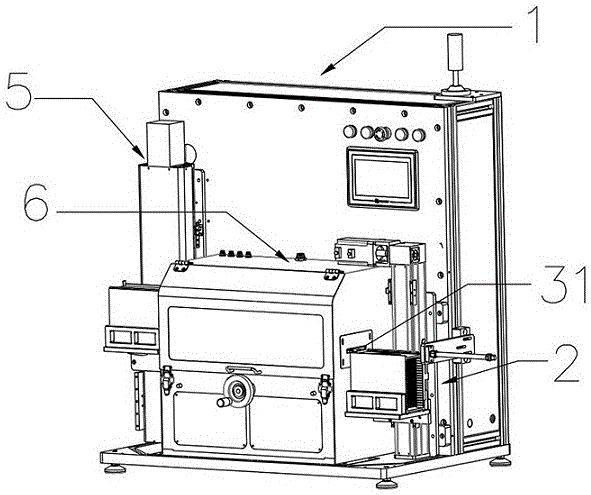
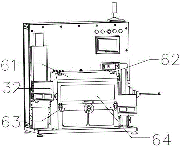
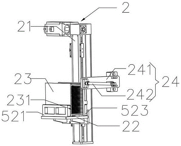
[0027] The automatic blow dryer described in this embodiment includes a frame 1, the frame 1 is provided with a feeding unit 2 for carrying the material to be dried, a conveying unit 3 for conveying the material, and The drying unit 4 for air-drying the web is a discharge unit 5 for carrying the dried material; the feeding unit 2 is arranged at the entrance 31 of the conveying unit, and the discharging unit 5 is arranged at The outlet end 32 of the transfer unit. Such as figure 1 , figure 2 , Figure 5 As shown, the specific working process is as follows: a person skilled in the art places a plurality of sheets to be blown-dried neatly on the feeding unit 2, and the feeding unit 2 feeds the sheets to be blown dry by a rising action To the inlet end 31 of the conveying unit and push the material to be blown into the conveying unit 3. The shell 6 is used to isolate most of the moisture in the outside atmosphere, so that a relatively dry space environment is formed in the drying unit 4 and the conveying unit 3, which is beneficial to the rapid drying of the material. The conveying unit 3 is used for conveying and fixing the material to be dried to the lower end of the drying unit 4, and the drying unit 4 air-drys various parts of the material by reciprocating movement to make the surface of the material dry. When the drying operation is completed, the drying unit 4 is reset, and the dried material is conveyed to the outlet end 32 of the conveying unit through the conveying unit 3, and the dried material is pushed onto the discharging unit 5. After the discharging unit 5 receives a piece of dried material, it lowers a station. Complete the entire drying operation. At the same time, the feeding unit 2 raises a station to send the next piece of material to be dried to the inlet end 31 of the conveying unit, and repeat the above steps until all the material has been dried.
[0028] In this embodiment, the drying unit 4 includes a fixing frame 41, a sliding mechanism 42, a sliding frame 44, and an air outlet assembly. The sliding mechanism 42 is fixed to the frame 1 through the fixing frame 41, and the sliding frame 44 and The sliding mechanism 42 is slidingly connected;
[0029] The air outlet assembly includes an air knife 43, an air inlet pipe, and an air tank. One end of the air knife 43 is provided with an angle adjustment block 45. The angle adjustment block 45 is movably connected to the sliding frame 44. The air inlet of the air knife 43 is fixedly connected, and the cylinder is fixedly connected to the other end of the intake pipe. When it is necessary to blow dry the material, such as figure 1 , Figure 7 As shown, the sliding frame 44 is driven to move back and forth by the sliding mechanism 42, and at the same time, the air knife 43 is realized under the action of the air tank (not shown in the drawing) and the air inlet pipe (not shown in the drawing) The function of the wind, thereby reducing the humidity in the air in the housing 6, forms a relatively dry space, and then performs repeated air-drying actions on the surface of the web. Until the blank is completely dry, when the drying action is completed, the air knife 43 is reset by the sliding frame 44. So as to complete the entire drying process. The angle adjusting block 45 can manually adjust the shape of the air knife 43, thereby adjusting the angle of the air outlet of the air knife 43, which is beneficial to the operation of the air-dried material and improves the efficiency of air-drying.
[0030] In this embodiment, the transfer unit 3 includes a first fixing plate 33, a second fixing plate 34, an adjusting plate 35, and a screw 36. The first fixing plate 33, the second fixing plate 34 and the screw 36 are movably connected The adjusting plate 35 is threadedly connected with the screw rod 36; one end of the screw rod 36 is provided with a hand rocker 361 for adjusting the width between the first fixing plate 33 and the adjusting plate 35. Such as Image 6 As shown, in order to adapt to different sizes of material, the technician can rotate the screw 36 by shaking the hand lever 361, and then move the adjusting plate 35, so that the width between the first fixing plate 33 and the adjusting plate 35 changes. The width between the first fixing plate 33 and the adjusting plate 35 can be adjusted according to different sizes of blanks. The invention is able to convey and blow dry materials of various sizes. Further, the hand rocker 361 can be replaced by a motor or an air cylinder, so that the width adjustment changes from manual operation to automatic operation.
[0031] In this embodiment, the inlet end 31 of the transfer unit is provided with a feed sensor 311, and the outlet end 32 of the transfer unit is provided with a discharge sensor 321; one side of the first fixing plate 33 is opposite to the adjusting plate 35 A conveyor belt 38 is provided on the corresponding side, the first fixed plate 33 is provided with a transmission drive mechanism 39, and a positioning block 310 is provided between the first fixed plate 33 and the adjusting plate 35; both sides of the positioning block 310 A positioning baffle 3101 is provided. The lower end of the positioning block 310 is provided with a positioning sensor 3102 and a blocking column 3103. The positioning sensor 3102 is fixedly arranged on one side of the positioning block 310, and the blocking column 3103 is fixedly arranged on the positioning block 310. On both sides. Such as Image 6 As shown, when the material is pushed to the entrance end 31 of the conveying unit, the feed sensor 311 senses the material and triggers the driving mechanism 39 to turn on, and the conveyor belt 38 moves the material to the direction of the positioning block 310. When the material is transferred to the positioning block 310, the positioning sensor 3102 senses the material and triggers the conveyor belt 38 to decelerate to a stop. At the same time, the positioning sensor 3102 triggers the blocking column 3103 to automatically bounce up, blocking the material from continuing to move, and finally The material is stopped at the upper end of the positioning block 310 for drying operation. After the drying operation is completed, the conveyor belt 38 continues to move the material in the direction of the outlet end 32 of the conveyor unit until it is pushed onto the discharge unit 5. When the discharging sensor 321 senses the material, the electric push rod 242 is triggered to push the next material into the entrance 31 of the conveying unit. And repeat the above steps to realize the automatic operation of conveying the material.
[0032] In this embodiment, the feeding unit 2 includes a first lifting mechanism 21, a first loading platform 22, and a feeding loading box 23 that cooperates with the first loading platform 22. A loading table 22 is slidably connected; the feeding unit 2 further includes a pushing mechanism 24, the pushing mechanism 24 includes a fixing member 241 and an electric push rod 242, the fixing member 241 is fixedly connected to the frame 1, the electric The push rod 242 is fixedly connected with the fixing member 241; on both sides of the inner wall of the feeding box 23 are provided a number of grooves 231 for lifting the sheet, and each two grooves 231 on the same side are provided Certain spacing. Such as image 3 As shown, the feeding carrier box 23 makes a plurality of sheets to be blown dried neatly placed in the feeding carrier box 23 in a manner of being inserted into the groove 231. The gap can ensure that there is enough space between adjacent blanks. The first loading platform 22 is used to carry the feeding cassette 23, and driven by the first lifting mechanism 21, the first loading platform 22 lifts the feeding cassette 23. The materials in the feed carrier box 23 can be moved to the entrance end 31 of the conveying unit 3 smoothly and sequentially. The fixing member 241 is used to fix the electric push rod 242 to the frame 1, so that the electric push rod 242 is aligned parallel to the entrance end 31 of the conveying unit, so that the electric push rod 242 can smoothly feed the cassette 23 every time. The material is pushed into the entrance end 31 of the conveying unit. Such as image 3 As shown, one side of the first loading platform 22 is provided with a fixed baffle 523, and the other side of the first loading platform 22 is provided with a movable baffle 521, which is used according to the difference of the feeding cassette 23 Adjust the position of the movable baffle 521 to change the distance between the fixed baffle 523 and the movable baffle 521 to achieve the effect of clamping the feeding carrier 23.
[0033] In this embodiment, the discharging unit 5 includes a second lifting mechanism 51, a second loading platform 52, and a discharge loading box 53 that cooperates with the second loading platform 52. The second lifting mechanism 51 and the first The two loading platforms 52 are slidably connected. Such as figure 2 , Figure 4 As shown, the conveying unit 3 is used to convey the blow-dried material to the outlet end 32 of the conveying unit, and to push the material into the discharge carrier box 53 in sequence. The shape of the discharge carrier box 53 and the inlet The material carrier box 23 is consistent, so that the material can be placed in the discharge carrier box 53 smoothly. The second lifting mechanism 51 is used for lifting and lowering the material carrier box 53. When the dried material is pushed When the material carrier box 53 is discharged, the second lifting mechanism 51 is triggered, so that the second lifting mechanism 51 is lowered to a station for preparing to receive the next piece of dried material. So as to realize the automatic operation of discharging storage. Such as Figure 4 As shown, one side of the second loading platform 52 is provided with a fixed baffle 523, and the other side of the second loading platform 52 is provided with a movable baffle 521, which is used according to the difference of the discharge cassette 53 Adjust the position of the movable baffle 521 to change the distance between the fixed baffle 523 and the movable baffle 521 to achieve the effect of clamping the discharge carrier box 53.
[0034] In this embodiment, a housing 6 is provided on the outside of the drying unit 4 and the conveying unit 3, and the housing 6 is provided with a side door 61, a hinge 62 and a snap lock 63. The side door 61 and the housing 6 The side door 61 and the housing 6 are movably connected by a hinge 62 through the hasp lock 63 locked, and the side door 61 is provided with an observation window 64. Such as figure 2 , Figure 4 As shown, the side door 61 is convenient for technicians to open the housing 6 to adjust the angle of the air knife 43, to repair and replace the air knife 43, or to clean the blow-drying unit 4. The buckle lock 63 is used to lock the side door 61 to form a relatively dry working space. The observation window 64 is convenient for technicians to monitor the working process of the drying operation.
[0035] In this embodiment, the outlet end 32 of the conveying unit is provided with a wind deflector 37, such as Figure 5 As shown, when the belt conveys the material to the outlet end 32 of the conveying unit, the remaining air of the air knife 43 is prevented from blowing away the material. As a preference, such as Image 6 As shown, the transmission driving mechanism 39 is provided with a sealed box 391 for protecting the driving motor from water and dust.
[0036] In this embodiment, the power sources of the first lifting mechanism 21, the second lifting mechanism 51, the pushing mechanism 24, the transmission drive mechanism 39, and the sliding mechanism 42 are cylinders or motors, and the principles are consistent with the known technology, and will not be omitted here. Go into details.
[0037] The present invention can realize the automatic conveying of the material through the feeding unit 2 and the discharging unit 5, and improve the automatic operation level; a relatively dry environment is formed through the shell 6 to facilitate rapid drying; and the drying unit 4 is used for drying The blow-drying operation can perform multi-angle, automatic and uniform blow-drying operations on the material to improve work efficiency and blow-drying quality.
[0038] Finally, it should be noted that the above embodiments are only used to illustrate the technical solutions of the present invention, rather than to limit the scope of protection of the present invention. Although the present invention has been described in detail with reference to preferred embodiments, those of ordinary skill in the art should understand The technical solution of the invention can be modified or equivalently replaced without departing from the essence and scope of the technical solution of the invention.

PUM

no PUM

Description & Claims & Application Information

We can also present the details of the Description, Claims and Application information to help users get a comprehensive understanding of the technical details of the patent, such as background art, summary of invention, brief description of drawings, description of embodiments, and other original content. On the other hand, users can also determine the specific scope of protection of the technology through the list of claims; as well as understand the changes in the life cycle of the technology with the presentation of the patent timeline. Login to view more.

Similar technology patents

Pyromellitic dianhydride teaching factory for teaching and training

InactiveCN105336261AIncrease awarenessImprove operational levelEducational modelsChemical plantManufacturing engineering
Owner:NANJING COLLEGE OF CHEM TECH

Method for converter steelmaking by directly using bottom slag produced by converter

ActiveCN105112598AAvoid splash accidents and safety hazardsImprove operational levelManufacturing convertersRecycling and recovery technologiesScrapSmelting
Owner:SHANDONG IRON & STEEL CO LTD

Digestive endoscopy simulator inspection quality evaluation method and system

PendingCN113763360AImprove efficiency and accuracy of assessmentsImprove operational levelImage enhancementImage analysisInspection timeDigestive endoscope
Owner:SHANDONG UNIV

Customs clearance face, fingerprint and identity card automatic authentication system and method

PendingCN111062270AImprove operational levelReduce subjective judgment participationData processing applicationsProgram loading/initiatingAuthentication systemLibrary management
Owner:SHENZHEN CASTEL INTELLIGENT TECH

Classification and recommendation of technical efficacy words

  • Improve operational level
  • Improve work efficiency

Customs clearance face, fingerprint and identity card automatic authentication system and method

PendingCN111062270AImprove operational levelReduce subjective judgment participationData processing applicationsProgram loading/initiatingAuthentication systemLibrary management
Owner:SHENZHEN CASTEL INTELLIGENT TECH

Pyromellitic dianhydride teaching factory for teaching and training

InactiveCN105336261AIncrease awarenessImprove operational levelEducational modelsChemical plantManufacturing engineering
Owner:NANJING COLLEGE OF CHEM TECH

Method for converter steelmaking by directly using bottom slag produced by converter

ActiveCN105112598AAvoid splash accidents and safety hazardsImprove operational levelManufacturing convertersRecycling and recovery technologiesScrapSmelting
Owner:SHANDONG IRON & STEEL CO LTD

Improved novel energy automobile charging device

Owner:XIAMEN YINLV JIEYUAN ENVIRONMENTAL PROTECTION TECH CO LTD
Why Eureka
Try Eureka