A Method for Rapid Measurement and Stakeout of High-rise Buildings

A technology for surveying lofting and high-rise buildings, applied in the field of architectural surveying and mapping, can solve the problems of lower precision of the main control axis of the construction floor, lower precision of the plummet, and low construction efficiency, so as to avoid secondary construction phenomena, improve accuracy, and improve The effect of construction efficiency

Active Publication Date: 2019-07-05
THE 4TH CONSTR ENG CO LTD OF CHINA RAILWAY NO 4 ENG GRP
View PDF5 Cites 2 Cited by
  • Summary
  • Abstract
  • Description
  • Claims
  • Application Information

AI Technical Summary

Problems solved by technology

[0004] 1. During the construction process, each floor should reserve holes for the laser plummet to shoot. After the main structure is completed, each reserved hole must be filled, and there is a phenomenon of secondary construction;
[0005] 2. In the process of stakeout, in order to ensure the smoothness of the laser projection point, the reserved holes on each layer must not be covered, and there are safety hazards such as falling objects and hurting people;
[0006] 3. During the construction process, first use the laser plummet to project the main control points to the floors to be constructed, and then use the total station (or theodolite) to release the vertical mold lines of the structures on the floors, which results in low construction efficiency;
[0007] 4. Stakeout coordinates or angles and distances need to be calculated;
[0008] 5. As the height of the construction floor increases, the accuracy of the plummet will decrease with the increase of the projection height, thus reducing the accuracy of the main control axis of the construction floor

Method used


Image

  • A Method for Rapid Measurement and Stakeout of High-rise Buildings
  • A Method for Rapid Measurement and Stakeout of High-rise Buildings
  • A Method for Rapid Measurement and Stakeout of High-rise Buildings

Examples


Embodiment Construction

[0026] A preferred embodiment of the present invention will be described in detail below with reference to the accompanying drawings.

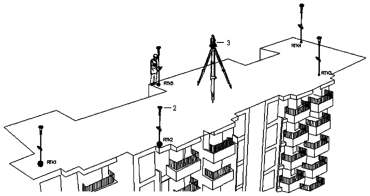
[0027] Set up the GPS-RTK reference station in a relatively open place on the construction site, set up the measurement robot 3 in the middle of the construction floor, and set up the GPS-RTK rover station 2 in any position as far as possible around it.

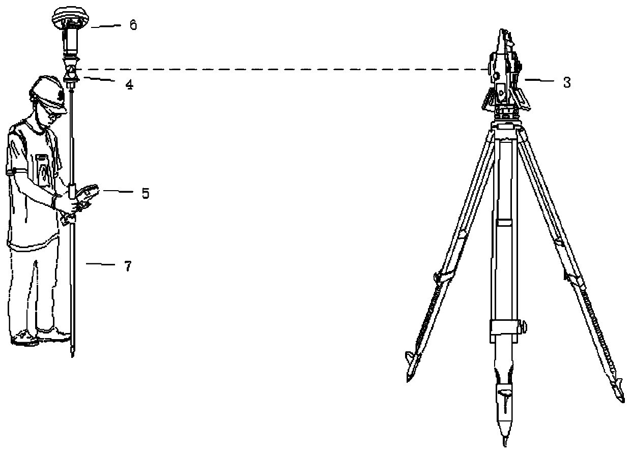
[0028] Such as figure 2 As shown in , the GPS-RTK rover 2 includes a receiver 6 and a connecting rod 7 for support, the upper end of the connecting rod is connected to the receiver through a full prism 4, and the connecting rod is provided with a measurement for generating a BIM model Hand thin 5, the BIM model can automatically generate the structural position that needs to be staked out.

[0029] The inventive method comprises the steps:

[0030] Step 1: Set up a GPS-RTK reference station in an open and interference-free place on the construction site.

[0031] Step 2: Set up the measur...


PUM


Abstract

The invention provides a rapid survey and setting-out method for high-rise buildings. The rapid survey and setting-out method comprises the following steps: erecting a GPS-RTK (Global Positioning System-Real-time Kinematic) base station on an empty place of a construction site; erecting a survey robot at a middle position of a construction floor; setting at least four control points at the periphery of the construction floor by utilizing a GPS-RTK mobile station; transmitting a coordinate of each control point to the survey robot to finish oriented work of a free station; finally, obtaining a structure position of a floor needing to be subjected to setting-out by utilizing a BIM (Building Information Modeling) technology; finishing the setting-out of a main control axis of the floor and a formwork erecting line of a structure through the survey robot. The rapid survey and setting-out method is simple to operate and convenient to use; automatic, paperless and visualized three-dimensional setting-out of construction buildings is really realized, and the setting-out efficiency and setting-out precision of the main control axis of each floor and the formwork erecting line of the structure are improved; the accuracy of a setting-out result is ensured from the source; meanwhile, the safety problem of falling objects is also avoided.

Description

technical field [0001] The invention relates to the technical field of building surveying and mapping, in particular to a method for rapid measurement and setting out of high-rise buildings. Background technique [0002] With the acceleration of urbanization, there are more and more high-rise and super high-rise buildings. In the process of setting out the main control axis of the floor and the vertical mold line of the structure, it is still not possible to fully realize the automatic, paperless and visualized three-dimensional setting out. . [0003] In the prior art CN105575249A, the currently commonly used stakeout method is as follows: four main control axis points are measured and set at the four corners of the first floor or the bottom floor, and holes are reserved on each floor at their corresponding positions, and the laser plummet is used to project points upward. Function and total station (or theodolite) axis measurement function, respectively lead the main cont...

Claims


Application Information

Patent Timeline
Patent Type & Authority Patents(China)
IPC IPC(8): G01C15/00G01S19/14
CPCG01C15/00G01S19/14
Inventor 童鹏程刘坤王根杰韩飞落陈小文高媛刘奎詹涛涛刘英营都永波
Owner THE 4TH CONSTR ENG CO LTD OF CHINA RAILWAY NO 4 ENG GRP
Why Eureka
Try Eureka