Weighing and batching system

A batching system and material hole technology, which is applied in the field of material batching system, can solve the problems of low weighing accuracy and long weighing time, and achieve the effect of high precision

Active Publication Date: 2017-06-13
NANO PHARM TECH MACHINERY EQUIP
View PDF9 Cites 6 Cited by
  • Summary
  • Abstract
  • Description
  • Claims
  • Application Information

AI Technical Summary

Problems solved by technology

[0004] The purpose of the present invention is to solve the problems of low weighing accuracy and long weighing time in the existing weighing and batching method

Method used


Image

  • Weighing and batching system
  • Weighing and batching system
  • Weighing and batching system

Examples


specific Embodiment approach 1

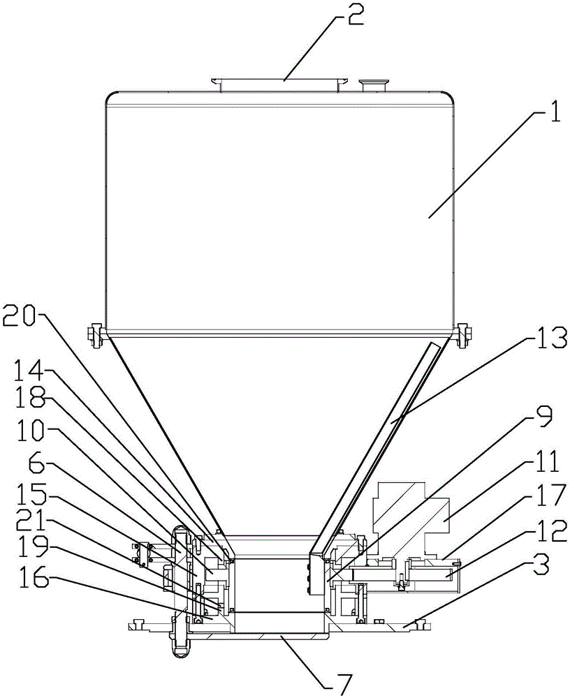
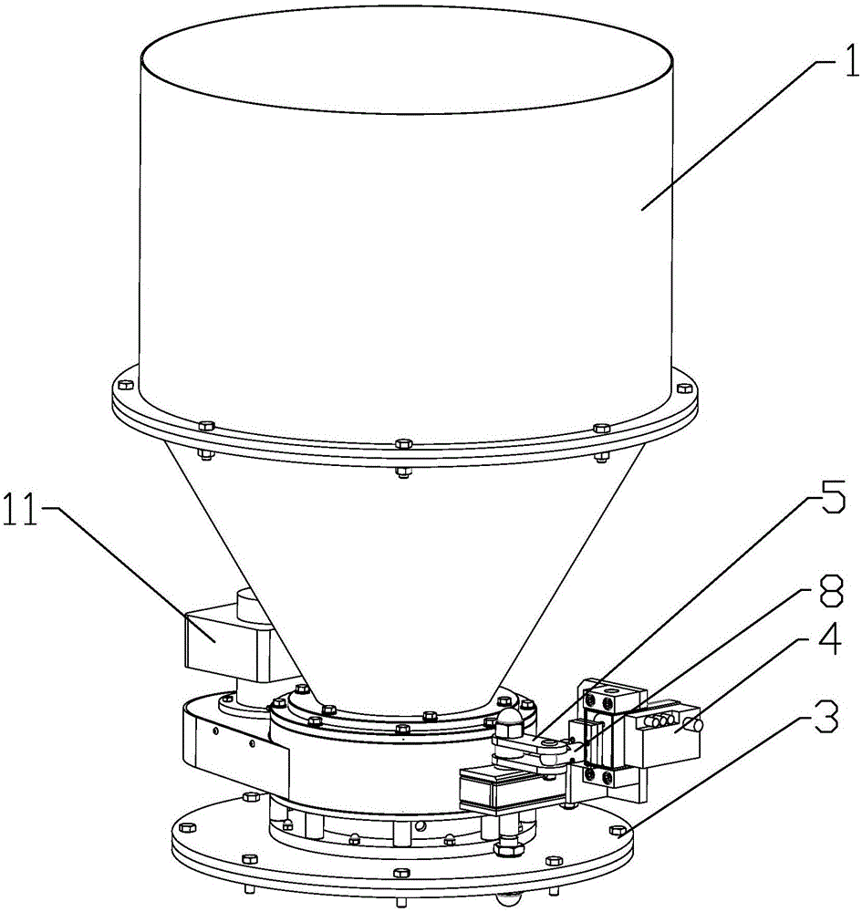
[0031] Specific implementation mode one: combine figure 1 , figure 2 and Figure 4 Describe this embodiment, this embodiment includes a batching device, the batching device includes a material storage tank 1, the upper part of the material storage tank 1 is cylindrical, and the lower part of the material storage tank 1 is cone-shaped, which is convenient for the material to be placed inside it. drop, the top of the storage tank 1 is provided with a feed port 2, and the bottom of the storage tank 1 is provided with a discharge port, and it also includes a flange 3, a connecting rod 5, a rotating shaft 6, a discharge baffle 7 and Multi-point positioning cylinder 4, the flange 3 is provided with a discharge hole, the discharge port is connected with the discharge hole, the multi-point positioning cylinder 5 is installed above the flange 3, the The rotating shaft 6 vertically passes through the flange 3 and rotates with the flange 3. The top of the rotating shaft 6 is hinged to...

specific Embodiment approach 2

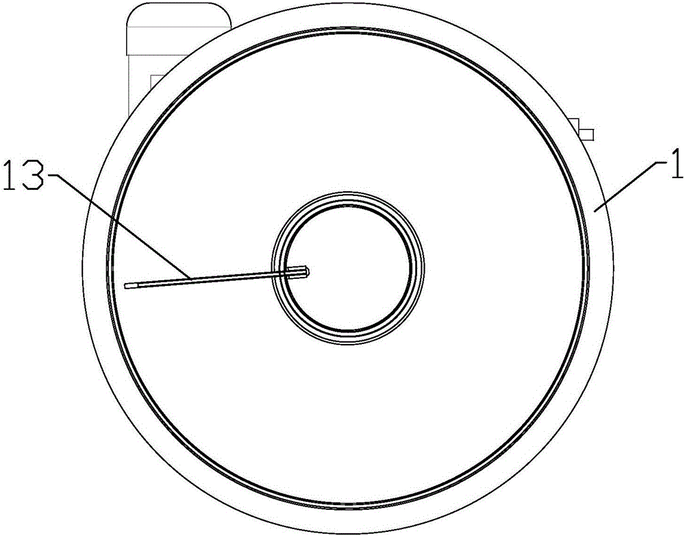
[0034] Specific implementation mode two: combination Figure 1 to Figure 3 To illustrate this embodiment, the batching device of this embodiment also includes a rotating sleeve 9, a driven gear 10, a motor 11, a driving gear 12 and a bridge breaking rod 13, and the rotating sleeve 9 is located between the storage tank 1 and the flange 3 There is an axial material channel between them, the upper end of the material channel communicates with the discharge port, the lower end of the material channel communicates with the discharge hole, and the driven gear 10 is coaxially and fixedly sleeved on the rotating shaft. The outer side of the cover 9, the bottom end of the bridge breaking rod 13 is fixedly connected to the inner wall of the rotating sleeve 9, and the bridge breaking rod 13 is inclined from the discharge port along the tapered inner wall of the storage tank 1 Stretch upwards in the described material storage tank 1, there is a gap between the bridge breaking rod 13 and t...

specific Embodiment approach 3

[0037] Specific implementation mode three: combination figure 1 Describe this embodiment, the dispensing device of this embodiment also includes a transition connector 14, a rotary sleeve shell 15, a rotary sleeve base 16 and a motor housing 17, the transition connector 14 is provided with an axial discharge hole, and the rotary The sleeve shell 15 and the rotating sleeve base 16 are hollow and the rotating sleeve base 16 is provided with an axial discharge channel. Up and down are sequentially coaxially fixed and sealed. The rotating sleeve shell 15 and the rotating sleeve base 16 form a hollow cavity. The rotating sleeve 9 and the driven gear 10 are located in the hollow cavity. The top of the rotating sleeve 9 is connected to the The bottom end of the transition connector 14 is docked and rotated, and the bottom end of the rotary sleeve 9 is docked and rotated with the top of the discharge channel of the rotary sleeve base 16. The discharge port, discharge hole, The materi...


PUM


Abstract

The invention provides a weighing and batching system, and relates to a batching system. The invention aims at solving the problem that an existing weighing and batching mode is low in weighing and batching precision and long in weighing and batching time consuming. The bottom end of a feed storage bucket (1) is provided with a feed outlet, an empting hole is formed in a flange disc (3), the feed outlet is communicated with the empting hole, a multi-point positioning air cylinder (5) is installed above the flange disc (3), a rotation shaft (6) vertically penetrates through the flange disc (3) and is rotatably matched with the flange disc (3), the top end of the rotation shaft (6) is hinged to one end of a connecting rod (5), the other end of the connecting rod (5) is hinged to a piston rod (8) of the multi-point positioning air cylinder (4), the bottom end of the rotation shaft (6) is fixedly connected to an empting baffle (7), and the upper surface of the empting baffle (7) is tightly attached to the lower surface of the flange disc (3). According to the weighing and batching system, the empting baffle is controlled by the multi-point positioning air cylinder, thus the purpose of opening empting holes with any size is quickly achieved, and the amount of fallen feed of the feed storage bucket is controlled. The weighing and batching system is used for weighing and batching materials.

Description

technical field [0001] The invention relates to a material batching system, in particular to a weighing and batching system with a fast weighing function of materials. Background technique [0002] There are mainly two ways of weighing and batching materials in the prior art, one of which is to weigh and batch manually, and the other is to weigh and batch by using screw conveying. The manual method of weighing ingredients does not meet the requirements of intelligent and unmanned production, and the accuracy is low and the process takes a long time. The weighing and batching is carried out by means of screw conveying. Since the weighing signal fed back by the electronic scale is used to control the conveying and batching action of the screw, affected by objective factors such as the thread pitch of the screw, the weighing accuracy is also low and the time-consuming is also long. , unable to meet the requirements of high-precision rapid weighing ingredients. [0003] To sum...

Claims


Application Information

Patent Timeline
Patent Type & Authority Applications(China)
IPC IPC(8): G01G19/38G01G19/30G01G23/00
CPCG01G19/30G01G19/38G01G23/00
Inventor 王孟刚
Owner NANO PHARM TECH MACHINERY EQUIP
Why Eureka
Try Eureka