
Globally optimized staggered mesh finite-difference forward simulation method and device

A staggered grid, finite difference technology, applied in the field of globally optimized staggered grid finite difference forward modeling, which can solve problems such as poor flexibility and application limitations

Inactive Publication Date: 2017-06-13
INST OF GEOLOGY & GEOPHYSICS CHINESE ACAD OF SCI
View PDF5 Cites 23 Cited by
  • Summary
  • Abstract
  • Description
  • Claims
  • Application Information

AI Technical Summary

Problems solved by technology

[0012] The embodiment of the present invention provides a globally optimized staggered grid finite difference forward modeling method to solve the technical problems of poor flexibility and application limitations existing in the scheme of optimizing the staggered grid finite difference operator in the prior art

Method used


Image

  • Globally optimized staggered mesh finite-difference forward simulation method and device
  • Globally optimized staggered mesh finite-difference forward simulation method and device
  • Globally optimized staggered mesh finite-difference forward simulation method and device

Examples


example 1

[0094] Example 1. The optimized 8th-order staggered grid finite difference operator is used to approximate the first space derivative, while the time first derivative is still calculated by the conventional second-order staggered grid difference operator. Formula (12) is solved to simulate elastic waves in Propagation in homogeneous isotropic media to verify its validity.

[0095] The grid size of the velocity model is 500×500, the horizontal and vertical grid intervals are 10m, the longitudinal wave velocity is 2500m / s, the shear wave velocity is 1700m / s, and the density is constant 1g / cm3; Ricker) wavelet point source is loaded on the vertical stress, excited at the center of the model, and the time sampling interval is 1ms. like Figure 6(a) , 6(b) , 6(c) and 6(d), it can be found that when the operator length is the same (same order), the optimized staggered grid finite difference operator simulates the dispersion of longitudinal and shear waves significantly worse than ...

example 2

[0096] Example 2. Using the complex marmousi2 model to verify the performance of suppressing the dispersion of the optimized 8th order staggered grid finite difference operator.

[0097] The Marmousi2 model size is 961*561, and its longitudinal wave velocity model is as follows Figure 7 As shown, the shear wave velocity is Given, the density is constant 1g / cm3. The Ricker wavelet with a main frequency of 38 Hz is used to excite near the surface (2.9976, 0.01249) Km; the horizontal and vertical grid intervals are both 6.245 m, and the time sampling interval is 0.5 ms. Figure 8(a) shows the vertical component wavefield records of the optimized 8th order staggered grid finite difference method and the conventional method with a total time length of 6 s. Among them, the left side is the 8th order conventional staggered grid finite difference simulation; the right side is 8th-order optimized staggered grid finite difference simulation; Figure 8(b) , 8(c) They are the enlarge...


PUM


Abstract

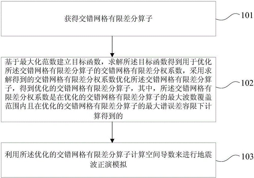
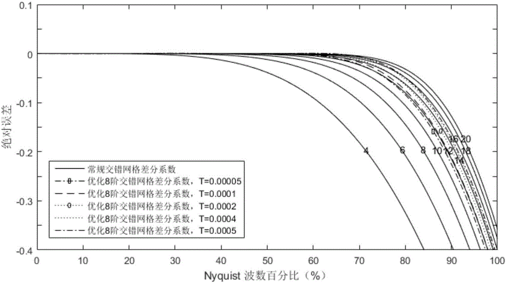
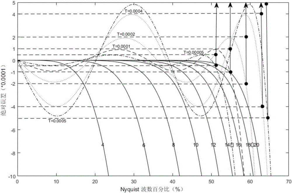
The embodiment of the invention provides a globally optimized staggered mesh finite-difference forward simulation method and device. The method comprises the steps that a staggered mesh finite-difference operator is obtained; a target function is established based on a maximized norm and is calculated to obtain a staggered mesh finite-difference decentralization coefficient for optimizing the staggered mesh finite-difference operator, wherein the staggered mesh finite-difference decentralization coefficient is calculated in the maximum wave number coverage range of the optimized staggered mesh finite-difference operator and under the maximum spectrum error margin of the optimized staggered mesh finite-difference operator; the calculated staggered mesh finite-difference decentralization coefficient is adopted to optimize the spatial staggered mesh finite-difference operator, and forward simulation of seismic waves is performed. By adopting the scheme, absolute spectrum errors of the optimized staggered mesh finite-difference operator are more flexibly controlled, numerical value frequency dispersion is more effectively constrained, and the seismic simulation precision is improved.

Description

technical field [0001] The invention relates to the technical field of seismic wave numerical simulation research, in particular to a globally optimized staggered grid finite difference forward modeling method and device. Background technique [0002] Seismic wave forward modeling is to simulate the propagation process of seismic waves in the earth's medium, and to study the relationship between the propagation characteristics of seismic waves and the parameters of the earth's medium, so as to achieve the optimal approximation to the actual observed seismic records. Due to the extreme complexity of the actual earth medium, it is difficult to obtain the analytical solution of the seismic wave equation. Therefore, the seismic wave numerical simulation method is the main method and technology for people to correctly understand the propagation law of seismic waves and verify the correctness of various hypothetical earth models; It has an important theoretical guiding role and p...

Claims


Application Information

Patent Timeline
IPC IPC(8): G01V1/28
CPCG01V1/28
Inventor 胡婷刘洪王之洋冯海新袁雨欣
Owner INST OF GEOLOGY & GEOPHYSICS CHINESE ACAD OF SCI
Learn More