Double layer quick energy-saving power distribution line deconcentrator

A technology for distribution lines and splitters, applied in circuits, electrical components, conductive connections, etc., can solve the problems of complicated operation and poor connection effect, and achieve the effect of simple connection method, convenient operation and strong clamping force

Inactive Publication Date: 2017-06-13
SHAOGUAN FANGSHENG ELECTRIC EQUIP CO LTD
View PDF1 Cites 3 Cited by
  • Summary
  • Abstract
  • Description
  • Claims
  • Application Information

AI Technical Summary

Problems solved by technology

The connection effect of this structu...

Method used


Image

  • Double layer quick energy-saving power distribution line deconcentrator
  • Double layer quick energy-saving power distribution line deconcentrator
  • Double layer quick energy-saving power distribution line deconcentrator

Examples


Embodiment Construction

[0025] The present invention will be further described below in conjunction with accompanying drawing and embodiment:

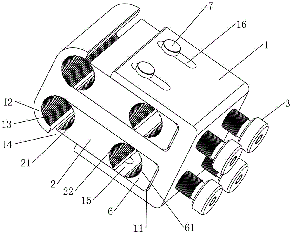
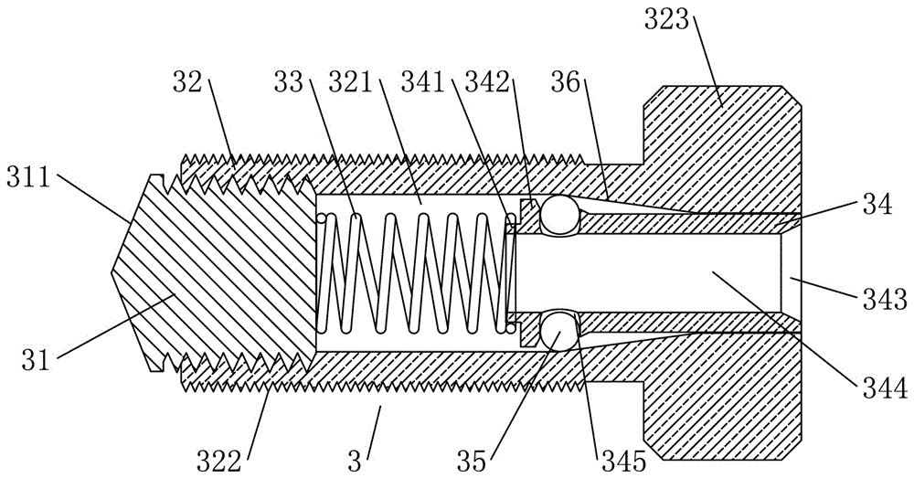
[0026] see figure 1 with figure 2 As shown, a double-layer fast energy-saving power distribution line splitter includes a main line conductive clip assembly, and the main line conductive clip assembly includes a clip jacket 1. Two slide chambers 11 are arranged side by side in the clip jacket 1, and two The sliding cavity 11 is provided with a crimping block 2 assembly, one end of the crimping block 2 assembly is provided with a dynamic crimping surface 21, and the end of the sliding chamber 11 opposite to the dynamic crimping surface 21 is provided with a constant crimping surface 12. A crimping groove 13 is formed between the line surface 21 and the constant pressure line surface 12, and the two sides of the jacket 1 respectively correspond to the constant pressure line surface 12 of each sliding chamber 11. Connected; it also includes the plug-in wire s...


PUM


Abstract

The invention relates to a double-layer fast energy-saving power distribution line splitter, which includes a main line conductive clip assembly. There is a crimping block assembly for sliding inside; it also includes a plug-in self-locking bolt assembly for pushing the crimping block assembly and connecting the branch line. Point to the other end of the wire crimping block assembly, that is, the self-locking bolt assembly of the plug-in wire is screwed into the screw hole from the outside to the inside, that is, there is a threading hole in the self-locking bolt assembly of the plug-in wire, and the threading hole is at least self-locking with the plug-in wire The outer end of the tightening bolt assembly is connected. The clamping method of each layer of this double-layer fast energy-saving distribution line splitter is the same as that of the single-layer splitter. However, after the two layers are integrated, it can have multiple splitter interfaces and can connect three The thicker sub-line above is suitable for some specific occasions.

Description

technical field [0001] The invention relates to a branch joint for electric power transmission, in particular to a double-layer fast energy-saving power distribution line splitter. Background technique [0002] Chinese Patent Document No. 106253168A disclosed a general-purpose shunt device on December 21, 2016, which includes a body, a U-shaped block, a first screw, a second screw, and an I-shaped block, and the main line is sequentially arranged on the body from left to right Groove, the first clamping block, the second screw hole, the I-block holding groove and the secondary line jack, the U-shaped mouth of the U-shaped block is clamped on the first clamping block, and the I-shaped block is rotated and fitted in the I-block clamping groove Inside, a second through hole is provided on the I-shaped block, and the second screw passes through the second through hole and threadedly fits with the second screw hole. One end of the U-shaped block is provided with an arc that match...

Claims


Application Information

Patent Timeline
IPC IPC(8): H01R4/38H01R4/48H01R11/32
CPCH01R4/38H01R4/4872H01R11/32
Inventor 曹孝培湛念军
Owner SHAOGUAN FANGSHENG ELECTRIC EQUIP CO LTD
Why Eureka
Try Eureka