Turbine-generator rotor adopting sub-slot air supplying and transverse wind gap cooling mode

A steam turbine generator and transverse wind technology, applied in wind power generation, electrical components, electromechanical devices, etc., can solve the problems of complicated fan design and installation, and achieve better cooling effect.

Active Publication Date: 2017-06-13
DONGFANG ELECTRIC MACHINERY
View PDF11 Cites 7 Cited by
  • Summary
  • Abstract
  • Description
  • Claims
  • Application Information

AI Technical Summary

Problems solved by technology

The fan design and installation of this kind of generator are complicated, and the ventilation loss is much higher than that of other models. The rotor only has a small auxiliary groove near the end face for the cooling gas to enter the air inlet of the axial wind hole of the coil.

Method used


Image

  • Turbine-generator rotor adopting sub-slot air supplying and transverse wind gap cooling mode
  • Turbine-generator rotor adopting sub-slot air supplying and transverse wind gap cooling mode
  • Turbine-generator rotor adopting sub-slot air supplying and transverse wind gap cooling mode

Examples


Embodiment Construction

[0048] The following non-limiting examples illustrate the invention.

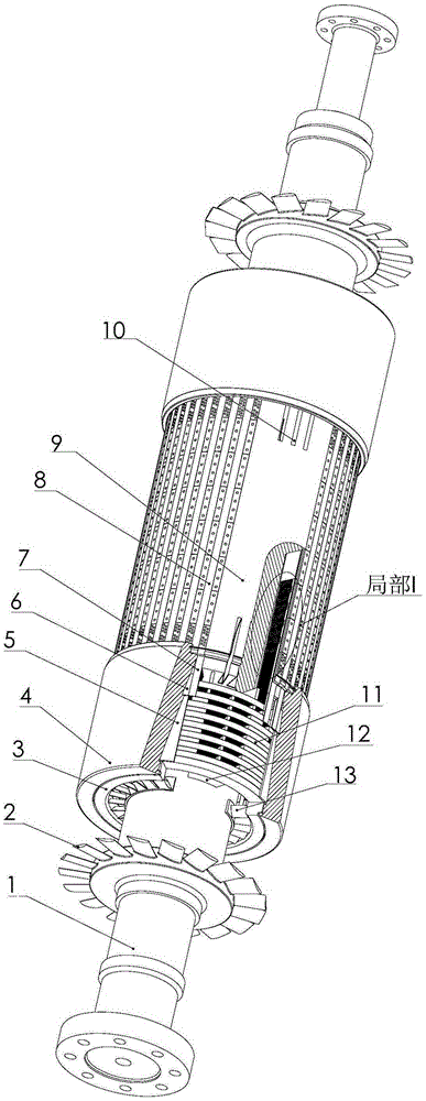
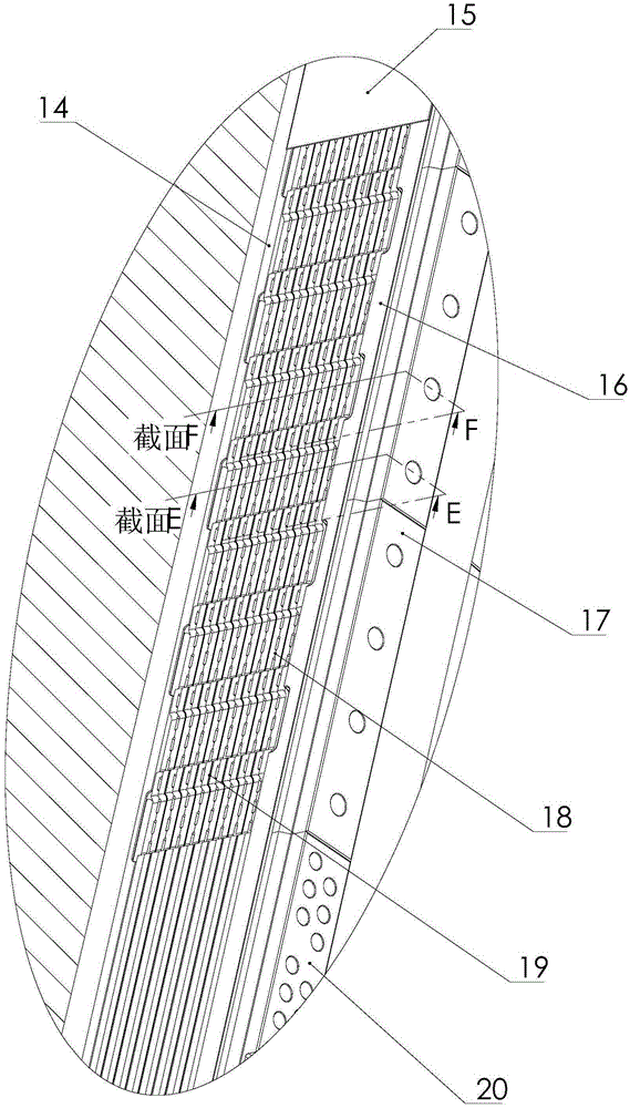
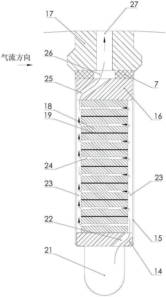
[0049] see Figure 1 to Figure 6 , the rotor of the present invention that adopts auxiliary slots for air supply and lateral air gap cooling, the rotor slot wedges 17 are flush with the rotor surface, the slot wedges 17 have no wind buckets (wind buckets, wind buckets), and the rotor teeth 9 / 10 have no wind buckets on the surface Horizontal ventilation slots. The fan 2 is installed at both ends of the rotating shaft 1, the rotor slot is embedded with a coil 18 (rotor copper wire turn), the slot wedge 17 and the rotor slot are in turn damping strips 7 and insulating pads 16 under the wedge, the bottom of the slot is milled Slot 21, between the wire slot and the auxiliary slot 21 is the slot bottom insulating pad 14, the end of the large tooth 9 is milled and thrown off the air slot 10; the slot bottom insulating pad 14, and the insulating pad 16 under the wedge, and the damping strip 7 in the slot and the ...


PUM


Abstract

The invention discloses a turbine-generator rotor adopting a sub-slot air supplying and transverse wind gap cooling mode, and belongs to the field of the generator rotor. Side edge radial air channels connected with slot wedge ventilating holes and a sub slot are formed in the two sides of a coil in a rotor wire slot respectively; transverse wind gaps, which are densely distributed in a radial direction in the coil, are connected with the side edge radial air channels in the two sides; the air flowing directions of the transverse wind gaps of adjacent pitches are opposite, and are perpendicular to the air flowing direction of the sub slot; axial air channels are formed in the straight line sections of an end part coil below each protective ring; end part slot wedge wind holes connected with the axial air channels and air gaps are formed in end part slot wedges; transverse air channels are formed in the arc sections of the end part coil; and wind blowing slots connected with the transverse air channels and the air gaps are formed in a big tooth end part. By adoption of the turbine-generator rotor with a novel ventilating structure, the problem existing in cooling of the full-speed turbine-generator rotor with single-machine power of 1,200MW or above can be solved.

Description

technical field [0001] The invention belongs to the field of generator rotors, and relates to a turbogenerator rotor with a novel ventilation structure, in particular to a full-speed turbogenerator with a single-stage fan pressure head with a unit power of more than 1200MW. Background technique [0002] Early turbogenerator rotors used external cooling. The heat generated by the coil was transferred to the outer surface of the rotor through heat conduction, and then transferred out through the convective heat dissipation of the cooling gas in the air gap. Due to the large heat transfer temperature difference of the externally cooled rotor, the single unit power of the generator can only reach 100MW; in order to meet the demand for continuous growth of unit capacity, the internally cooled rotors in the world that take air from the air gap and supply air from the auxiliary tank are currently being used. It is widely used in large-capacity turbogenerator products. in: [0003...

Claims


Application Information

Patent Timeline
Patent Type & Authority Applications(China)
IPC IPC(8): H02K1/32
CPCH02K1/32H02K2213/03Y02E10/72
Inventor 周光厚张海波
Owner DONGFANG ELECTRIC MACHINERY
Why Eureka
Try Eureka