Molding method using molding device to mold resin outer casing of stator unit and motor

A technology for stator units and resin shells, applied in electromechanical devices, manufacturing stator/rotor bodies, electrical components, etc., can solve the problems of incomplete coverage of resin, increased processing costs, and reduced production efficiency, achieving simple structure and reduced defect rate , the effect of increasing space

Inactive Publication Date: 2017-06-13
NIDEC SHIBAURA ZHEJIANG
View PDF5 Cites 0 Cited by
  • Summary
  • Abstract
  • Description
  • Claims
  • Application Information

AI Technical Summary

Problems solved by technology

[0003] The above molding method of the resin case of the stator unit has the following disadvantages: Since there is only a small gap between the teeth ends of the stator unit and the molding die, the inflow of the resin is prevented due to the small gap, which may cause the resin to not completely cover the stator The tooth ends of the unit, and the inner peripheral side of the stator unit may have a little resin infiltrated, and the resin solidifies and becomes a burr. If the burr is formed, it will interfere with the rotor, and the load on the rotor rotation will increase, so it needs to be removed. The rough work increases the processing cost and reduces the production efficiency

Method used


Image

  • Molding method using molding device to mold resin outer casing of stator unit and motor
  • Molding method using molding device to mold resin outer casing of stator unit and motor
  • Molding method using molding device to mold resin outer casing of stator unit and motor

Examples


Embodiment 1

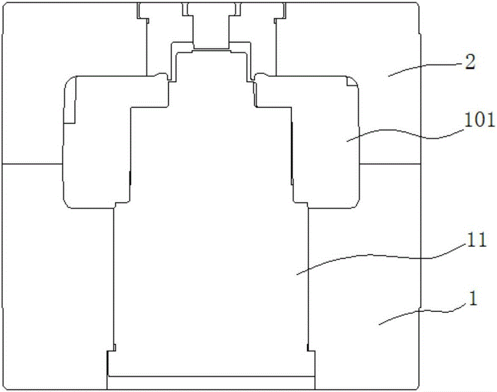
[0034] In the molding method for molding the resin shell of the stator unit using the molding device of this embodiment, the molding device is first prepared, see figure 1 , figure 1 It is a schematic cross-sectional view of a molding device, wherein the molding device has a cavity 101 for accommodating a stator unit, and has a first mold 1 , and the first mold 1 has a central mold 11 extending along the axial direction of the cavity 101 . A resin inlet is provided on the molding device, and the resin inlet communicates with the cavity 101 , so that resin can be injected into the cavity 101 from the resin inlet.

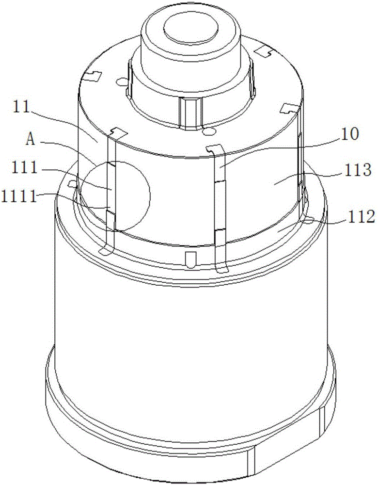
[0035] see figure 2 , figure 2 It is a schematic diagram of the three-dimensional structure of the central mold 11. Different positions in the circumferential direction of the central mold 11 have a plurality of contact portions 111, and the plurality of contact portions 111 protrude radially outward relative to the outer peripheral surface of the central mold 11...

Embodiment 2

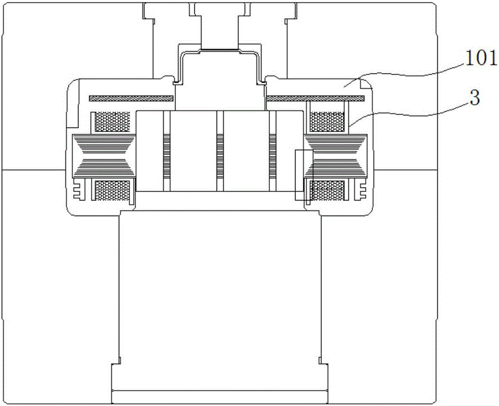
[0049] see Figure 5 and Figure 7 , Figure 5 It is a schematic cross-sectional view of a motor. The motor in this embodiment has a stator unit 3 and a resin case 4 molded by the method of molding the resin case of the stator unit using a molding device in the first embodiment. The stator unit 3 in this embodiment has a stator core 31, an insulator 32, and a coil 33. The stator core 31 has an annular core back 312 and a plurality of teeth extending radially inward from the core back 312. Section 311. The above is the prior art, which will not be repeated here.

[0050] The resin case 4 in this embodiment covers at least a part of the stator unit 3 , and the ends of the teeth 311 have a plurality of areas not covered by the resin case 4 . Here, the plurality of areas not covered by the resin case 4 is caused by the contact portion 111 of the molding device abutting against the tooth portion 211 , so that the position where the contact portion 111 abuts is not covered with ...


PUM


Abstract

The present invention proposes a molding method for molding a resin case of a stator unit by using a molding device and a motor. In the prior art, since there is only a small gap between the tip of the tooth and the mold, the inflow of resin is prevented. The present invention proposes a molding method for molding a resin shell of a stator unit using a molding device. The molding device has a cavity and a first mold. The first mold has a central mold. a plurality of contact parts protruding radially outward relative to the outer peripheral surface of the central mold and extending in the axial direction, and the plurality of contact parts have abutting surfaces, the molding method is characterized in that it includes the following steps: The stator unit is arranged in the cavity, and the abutment surfaces of the contact parts are abutted against the ends of the teeth of the stator unit; the resin shell of the stator unit is molded by a molding device. The invention has simple structure and reasonable design, and is not prone to the defects of burrs and uneven resin coverage.

Description

technical field [0001] The present invention relates to a molding method and a motor for molding a resin casing of a stator unit by using a molding device. Background technique [0002] The motor has a stator unit having a stator core, an insulating member, and a winding wire, and a resin case covering at least a part of the stator unit. The molding method of the resin shell of the stator unit in the prior art is formed by a molding die. During molding, the stator unit is arranged in the molding die, and the resin shell of the stator unit is formed by injecting the resin into the molding die and curing, and the stator unit A recess for insertion of the rotor is formed. During molding, the molding die abuts against the entire periphery of the ends of the teeth of the stator unit, and the center of the stator unit is formed as a concave portion after molding by injection of resin. [0003] The above molding method of the resin case of the stator unit has the following disadv...

Claims


Application Information

Patent Timeline
IPC IPC(8): H02K15/14H02K15/02H02K1/12H02K5/08
CPCH02K15/14H02K1/12H02K5/08H02K15/02
Inventor 贺国忠张建
Owner NIDEC SHIBAURA ZHEJIANG
Why Eureka
Try Eureka