Intake control device for an engine

a control device and engine technology, applied in the direction of combustion engines, combustion air/fuel air treatment, charge feed systems, etc., can solve the problems of limiting affecting the effect of tumbling flow, and affecting the flow of intake air, etc., to achieve the effect of simple construction

Inactive Publication Date: 2009-09-24
YAMAHA MOTOR CO LTD
View PDF11 Cites 16 Cited by
  • Summary
  • Abstract
  • Description
  • Claims
  • Application Information

AI Technical Summary

Benefits of technology

[0011]In order to overcome the problems described above, preferred embodiments of the present invention provide an intake control device for an engine, in which a further effective tumbling flow is generated in the cylinder with a simple construction.
[0014]According to a preferred embodiment of the present invention, when the tumble control valve is closed, intake air flows only into the intake passage below the partition plate. The bottom wall around the inlet of the lower intake passage is preferably inclined to be separated from the partition plate as it extends to the more upstream portion, and thus the inlet is wide and an inflow of intake air is facilitated.
[0019]When a strong tumbling flow is generated in the cylinder, a fuel-air mixture intensively flows in the combustion chamber at a point in the end period of a compression stroke and just before ignition thereby improving the conditions for combustion.
[0021]Therefore, in an engine including the intake control device according to the various preferred embodiments of the present invention, an effecting tumbling flow is generated for combustion by closing the tumble control valve as described above, and thereby fuel efficiency can be improved and generation of harmful substances can be minimized. Also, the engine can have a high speed and a high output by opening the tumble control valve.
[0022]According to a preferred embodiment of the present invention, intake air preferably flows into the cylinder through the lower intake passage in a state that the tumble control valve is closed. Thereby, a portion of the intake air, which hits the valve disc of the intake valve, flows in a direction opposite to the intake passage as seen along the axial direction of the crankshaft. Therefore, the intake air hits the valve disc of the intake valve, whereby intake air is prevented from flowing in a direction in which a tumbling flow is weakened, and thus a further effective tumbling flow can be generated.

Problems solved by technology

There is a limit to further generating an effective tumbling flow with the conventional intake control devices described above.
It is believed that the limit occurs because when the tumble control valve is closed, drag of intake air becomes large and the flow coefficient largely decreases.
Also, the conventional intake control devices have to include a movable flow straightening member and a partition plate to facilitate a tumbling flow, and thus its construction is complicated.

Method used


Image

  • Intake control device for an engine
  • Intake control device for an engine
  • Intake control device for an engine

Examples


Embodiment Construction

[0031]Preferred embodiments of the intake control device for an engine according to the present invention will be described in detail hereinafter with reference to FIGS. 1 through 7.

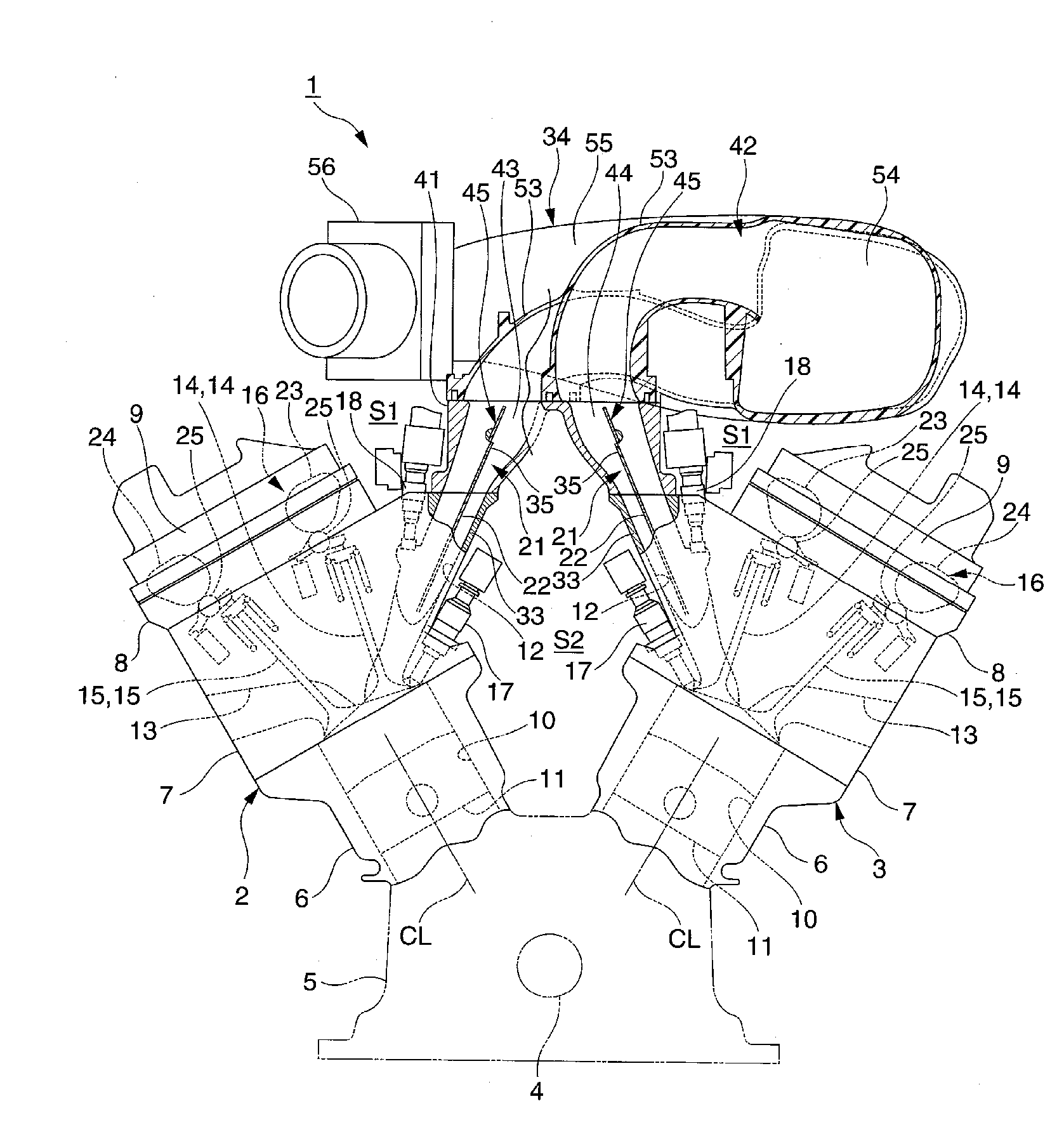
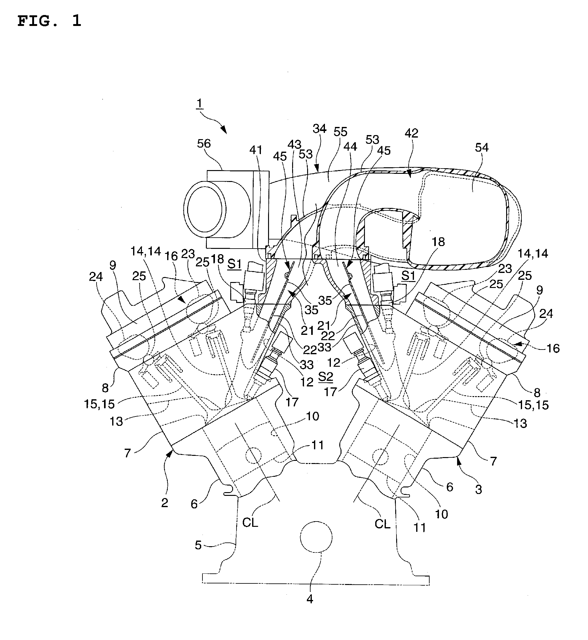
[0032]FIG. 1 is a front view of the engine including the intake control device according to a preferred embodiment of the present invention. In FIG. 1, an upstream portion of an intake passage is cut away. FIG. 2 is an enlarged cross-sectional view showing essential parts of the intake control device. FIG. 3 is an enlarged cross-sectional view showing an attachment part of an in-cylinder injector. FIG. 4 is a cross-sectional view of the intake passage taken along a line IV-IV in FIG. 2. In FIG. 4, the positions, along which the cross-section of FIG.2 is taken, are shown by a line II-II, and the positions, along which the cross-section of FIG. 3 is taken, are shown by a line III-III. FIGS. 5 through 7 are cross-sectional views of the intake passage. FIG. 5 is a cross-sectional view taken along a line V-V ...


PUM


Abstract

In an intake control device, upper and lower partition plates are provided in an intake passage extending obliquely upward from a combustion chamber as seen in an axial direction of a crankshaft. The partition plates divide the intake passage into upper intake passages and lower intake passages. A tumble control valve is arranged in an upstream vicinity of the partition plate in the intake passage. The tumble control valve opens or closes the upper intake passage. A bottom wall, which is a portion of a wall around an inlet of the lower intake passage and positioned on the side opposite to the upstream partition plate, is inclined to be gradually separated from the upstream partition plate as it extends upward.

Description

BACKGROUND OF THE INVENTION[0001]1. Field of the Invention[0002]The present invention relates to an intake control device for an engine for generating a tumbling flow of intake air in a cylinder.[0003]2. Description of the Related Art[0004]A conventional intake control device for an engine is disclosed in JP-A-2003-239751 (Patent Document 1) and JP-A-2003-278551 (Patent Document 2), for example. The intake control device for the engine disclosed in Patent Documents 1 and 2 includes a partition plate for partitioning an intake passage in an engine into an upper intake passage and a lower intake passage as seen along an axial direction of a crankshaft, and a tumble control valve provided in a vicinity of an upstream portion of the partition plate for opening or closing the lower intake passage.[0005]The intake control device disclosed in Patent Document 1 includes a flow straightening member for regulating a flowing direction of intake air while being linked with the tumble control va...

Claims


Application Information

Patent Timeline
Patent Type & Authority Applications(United States)
IPC IPC(8): F02M35/10
CPCF02B23/104F02B31/08Y02T10/146Y02T10/125F02B2023/106Y02T10/12
Inventor MAEDA, HIROYUKI
Owner YAMAHA MOTOR CO LTD
Why Eureka
Try Eureka