
Cable-type secondary battery

a secondary battery and cable-type technology, applied in the field of cable-type secondary batteries, can solve the problems of increasing poor flexibility of the battery, and the shape of the cylindrical, prismatic or pouch secondary batteries, so as to enhance the stability and performance of the cable-type secondary battery, reduce the resistance of the battery, and high resistance

Active Publication Date: 2014-12-25
LG ENERGY SOLUTION LTD
View PDF13 Cites 15 Cited by
  • Summary
  • Abstract
  • Description
  • Claims
  • Application Information

AI Technical Summary

Benefits of technology

The patent is about a new type of secondary battery that can change shape easily, and still perform well. It also allows for easier flow of electrolyte into the battery's active material.

Problems solved by technology

Because a predetermined mounting space for the electrode assembly is necessary in this process, the cylindrical, prismatic or pouch shape of the secondary batteries is a limitation in developing various shapes of mobile devices.
However, such battery has poor flexibility.
The linear batteries use a polymer electrolyte to form an electrolyte layer, but this causes difficulties in the inflow of the electrolyte into an electrode active material, thereby increasing the resistance of the batteries and deteriorating the capacity and cycle characteristics thereof.
Also, the cable-type batteries may have spaces that are ununiformly generated among a separation layer interposed between an inner electrode and an outer electrode and such electrodes in the preparation thereof, and such a space may disturb the introduction of an electrolyte solution in an outer electrode active material layer, thereby deteriorating battery performances.
In addition, in the case of cable-type batteries having a wire-form current collector, since a value of line resistance is generally higher than that of sheet resistance, the wire-form current collector may exhibit high resistance as compared with a sheet-form current collector, thereby deteriorating battery performances.

Method used


Image

  • Cable-type secondary battery
  • Cable-type secondary battery
  • Cable-type secondary battery

Examples


example

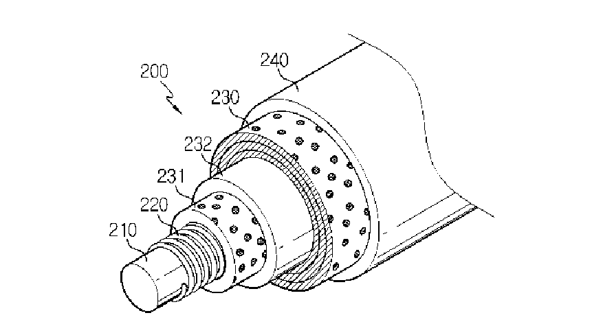
[0194]Four Cu-wires having a diameter of 250 μm were wound with crossing with each other to obtain an open-structured inner electrode supporter in which a hollow core for supplying lithium ions in the form of a spring can be present.

[0195]Then, 70 wt % of graphite as an anode active material, 5 wt % of Denka black as a conductive material and 25 wt % of PVdF as a binder were mixed to obtain an anode active material-containing slurry. The slurry was coated on a Cu-foil and slit into a piece with a width of 2 mm, to obtain a sheet-form inner electrode (anode).

[0196]Meanwhile, 80 wt % of LiCoO2 as a cathode active material, 5 wt % of Denka black as a conductive material and 15 wt % of PVdF were mixed to obtain a cathode active material-containing slurry. The slurry was coated on an Al-foil and slit into a piece with a width of 2 mm, to obtain a sheet-form outer electrode (cathode).

[0197]Next, the sheet-form inner electrode was adhered with a sheet-form separator consisting of a porous ...


PUM


Abstract

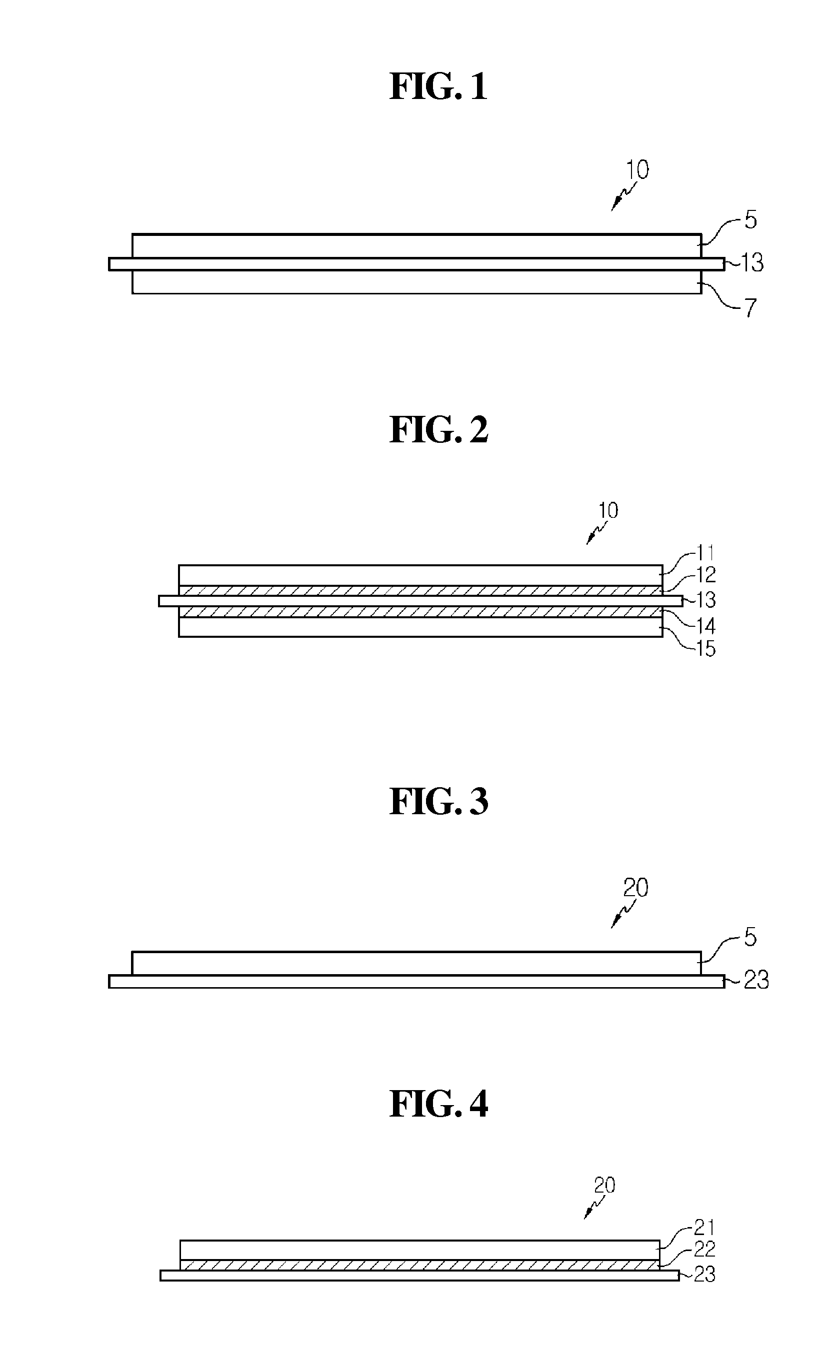
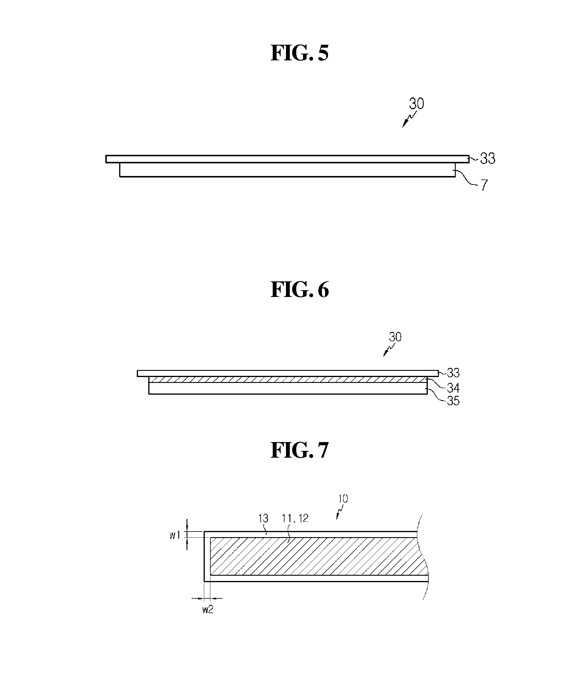
The present disclosure provides a cable-type secondary battery, comprising: an inner electrode supporter; and a sheet-form laminate of inner electrode-separation layer-outer electrode, spirally wound on the outer surface of the inner electrode supporter, wherein the laminate of inner electrode-separation layer-outer electrode is formed by carrying out compression for the integration of an inner electrode, a separation layer for preventing a short circuit, and an outer electrode. In the cable-type secondary battery of the present disclosure, since the electrodes and the separation layer are adhered to each other and integrated, the separation layer coming into contact with the electrodes absorbs an electrolyte solution to induce the uniform supply of the electrolyte solution into the outer electrode active material layer, thereby enhancing the stability and performances of the cable-type secondary battery.

Description

CROSS-REFERENCE TO RELATED APPLICATION[0001]This application is a continuation of International Application No. PCT / KR2014 / 004042 filed on May 7, 2014, which claims priority under 35 USC 119(a) to Korean Patent Application No. 10-2013-0051561 filed in the Republic of Korea on May 7, 2013, and Korean Patent Application No. 10-2014-0054275 filed in the Republic of Korea on May 7, 2014, the disclosure of which is incorporated herein by reference.TECHNICAL FIELD[0002]The present disclosure relates to a cable-type secondary battery which can freely change in shape, and more specifically to a cable-type secondary battery constructed to comprise an inner electrode supporter, and an integrated laminate of electrodes and a separation layer.BACKGROUND ART[0003]Secondary batteries are devices capable of storing energy in chemical form and of converting into electrical energy to generate electricity when needed. The secondary batteries are also referred to as rechargeable batteries because they...

Claims


Application Information

Patent Timeline
IPC IPC(8): H01M10/04H01M10/0525H01M10/0567H01M10/0565H01M10/0569H01M50/414H01M50/469
CPCH01M10/0422H01M10/0565H01M10/0525H01M10/0567H01M10/0569H01M4/13H01M4/366H01M4/70H01M4/75H01M10/052H01M10/0587H01M50/46H01M50/414H01M50/469H01M10/0436H01M4/622H01M4/626Y02E60/10Y02P70/50H01M10/058H01M4/78H01M4/667H01M4/668H01M2004/025H01M2300/0085H01M10/0468H01M4/74H01M4/66H01M10/056H01M2300/0017H01M50/463H01M2300/0082H01M10/0431H01M4/02H01M10/0568H01M10/125H01M10/286H01M2220/30H01M2300/0028
Inventor KWON, YO-HANOH, BYUNG-HUNJUNG, HYE-RANKIM, JE-YOUNG
Owner LG ENERGY SOLUTION LTD
Learn More