A direct current reciprocating thruster

A thruster, direct current technology, applied in the direction of electromechanical devices, electrical components, etc., can solve the problem that the motor cannot be solved, and achieve the effect of improving the conversion efficiency of electric energy and preventing the leakage of the magnetic field.

Inactive Publication Date: 2019-04-26
赵德连
View PDF5 Cites 0 Cited by
  • Summary
  • Abstract
  • Description
  • Claims
  • Application Information

AI Technical Summary

Problems solved by technology

[0003] The technical problem to be solved by the present invention is to provide a direct current reciprocating thruster, which utilizes the principle of electromagnetism to enable the movable coil frame to move horizontally reciprocatingly by switching the direction of the current, and can efficiently utilize direct current to generate mechanical energy, which solves the technical problem that cannot be solved by the motor

Method used


Image

  • A direct current reciprocating thruster
  • A direct current reciprocating thruster
  • A direct current reciprocating thruster

Examples


Embodiment Construction

[0018] Below in conjunction with specific embodiment, further illustrate the present invention. It should be understood that these examples are only used to illustrate the present invention and are not intended to limit the scope of the present invention. In addition, it should be understood that after reading the teachings of the present invention, those skilled in the art can make various changes or modifications to the present invention, and these equivalent forms also fall within the scope defined by the appended claims of the present application.

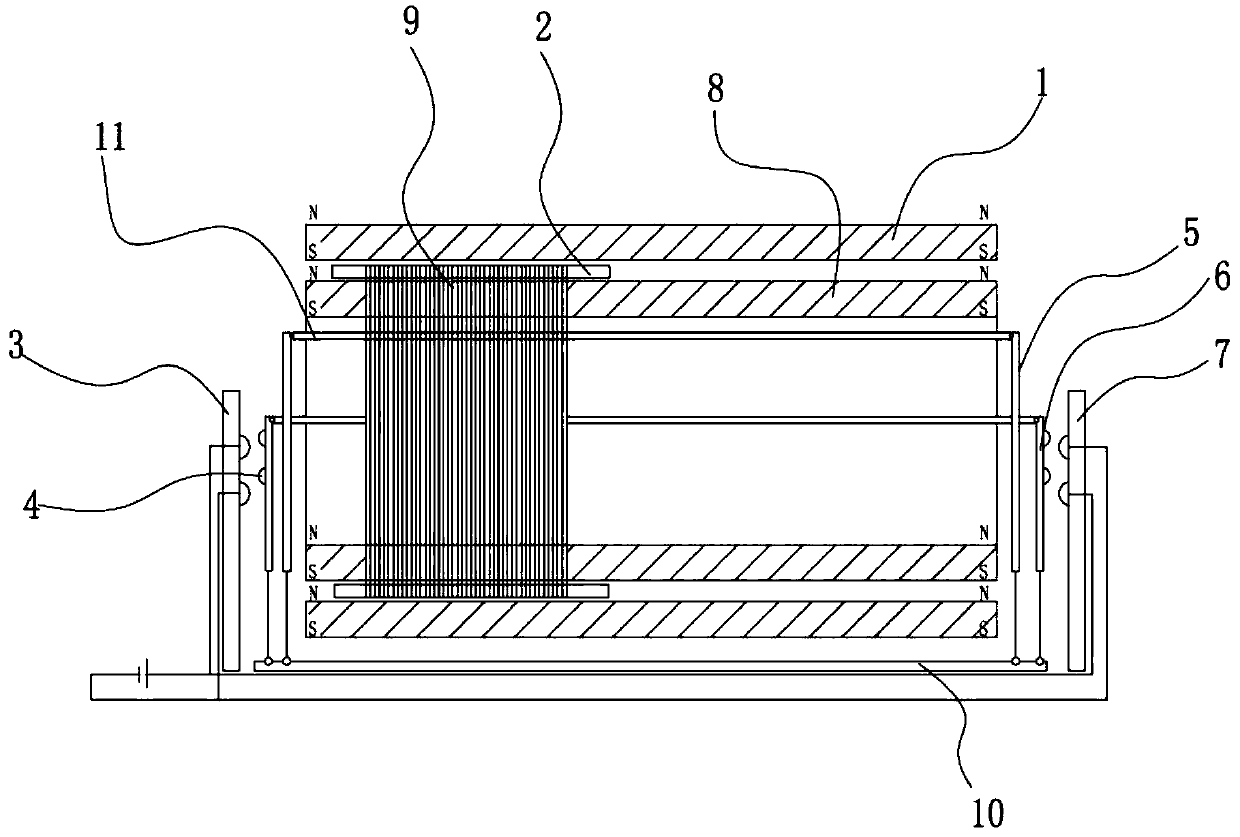
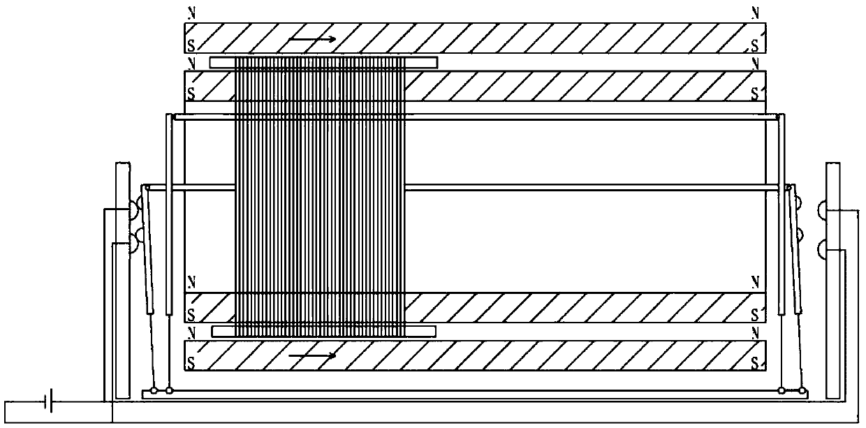
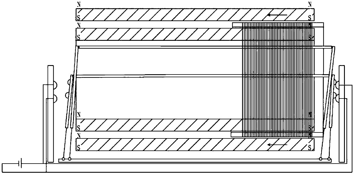
[0019] Such as Figure 1-5 As shown, the embodiment of the present invention relates to a DC reciprocating thruster, comprising a magnet group and a movable coil frame 2, the magnet group includes an outer magnet 1 and an inner magnet 8 arranged concentrically, and the outer magnet 1 and the inner magnet 8 have the same closed shape in cross-section, and one or more movable coil holders 2 with matching cross-sectional shapes a...


PUM


Abstract

The invention relates to a DC reciprocating thruster comprising a magnet group and a movable coil frame. The magnet group comprises an outer and an inner magnet which are concentrically arranged. The outer magnet and the inner magnet have the same cross section in a closed shape. The movable coil frame is arranged axially between the outer magnet and the inner magnet in a sliding way. The two ends of the magnet group are provided with a forward current switch frame and a reverse current switch frame respectively. Linked power swing switches are arranged symmetrically on both ends of the magnet group. Linked position swing switches are installed between the power swing switches and the forward current switch frame or between the power swing switches and the reverse current switch frame. The side surfaces, opposite to the forward current switch frame or the reverse current switch frame, of the position swing switches are provided with corresponding contacts. The DC reciprocating thruster enables the movable coil frame to perform horizontal reciprocating motion by switching current directions by means of an electromagnetic principle, can generate mechanical energy by efficiently utilizing direct current, and solves a technical problem that cannot be solved by a motor.

Description

technical field [0001] The invention relates to the field of direct current motion actuators, in particular to a direct current reciprocating thruster. Background technique [0002] As the main power source now, the motor is widely used. The motor uses alternating current. In many occasions, there is often no alternating current. For example, when directly using a battery to supply power to the motor, a current converter must be used to convert the direct current into alternating current before it can be used. Now There are also DC motors, but the efficiency of DC motors in converting electrical energy into mechanical energy is not high, resulting in relatively large energy waste, so now there is a need for a device that can efficiently convert DC electrical energy into mechanical kinetic energy. Contents of the invention [0003] The technical problem to be solved by the present invention is to provide a direct current reciprocating thruster, which utilizes the principle ...

Claims


Application Information

Patent Timeline
Patent Type & Authority Patents(China)
IPC IPC(8): H02K33/16
CPCH02K33/16
Inventor 赵德连
Owner 赵德连
Why Eureka
Try Eureka