Miniature grinding device for mechanical manufacturing design

A kind of mechanical manufacturing and miniature technology, which is applied in the field of micro-grinding devices for mechanical manufacturing design, can solve problems such as easy-to-produce errors, and achieve the effect of improving grinding efficiency and avoiding errors

Active Publication Date: 2022-06-24
NANTONG VOCATIONAL COLLEGE
View PDF5 Cites 1 Cited by
  • Summary
  • Abstract
  • Description
  • Claims
  • Application Information

AI Technical Summary

Problems solved by technology

[0005]In order to overcome the disadvantage that the existing grinding device relies on manual operation to complete the clamping work of mechanical parts and is prone to errors, the technical problem to be solved is: to provide a A micro-grinding device for mechanical manufacturing design that can automatically complete the clamping work of mechanical parts, thereby ensuring the orderly progress of the grinding work

Method used


Image

  • Miniature grinding device for mechanical manufacturing design
  • Miniature grinding device for mechanical manufacturing design
  • Miniature grinding device for mechanical manufacturing design

Examples


Embodiment 1

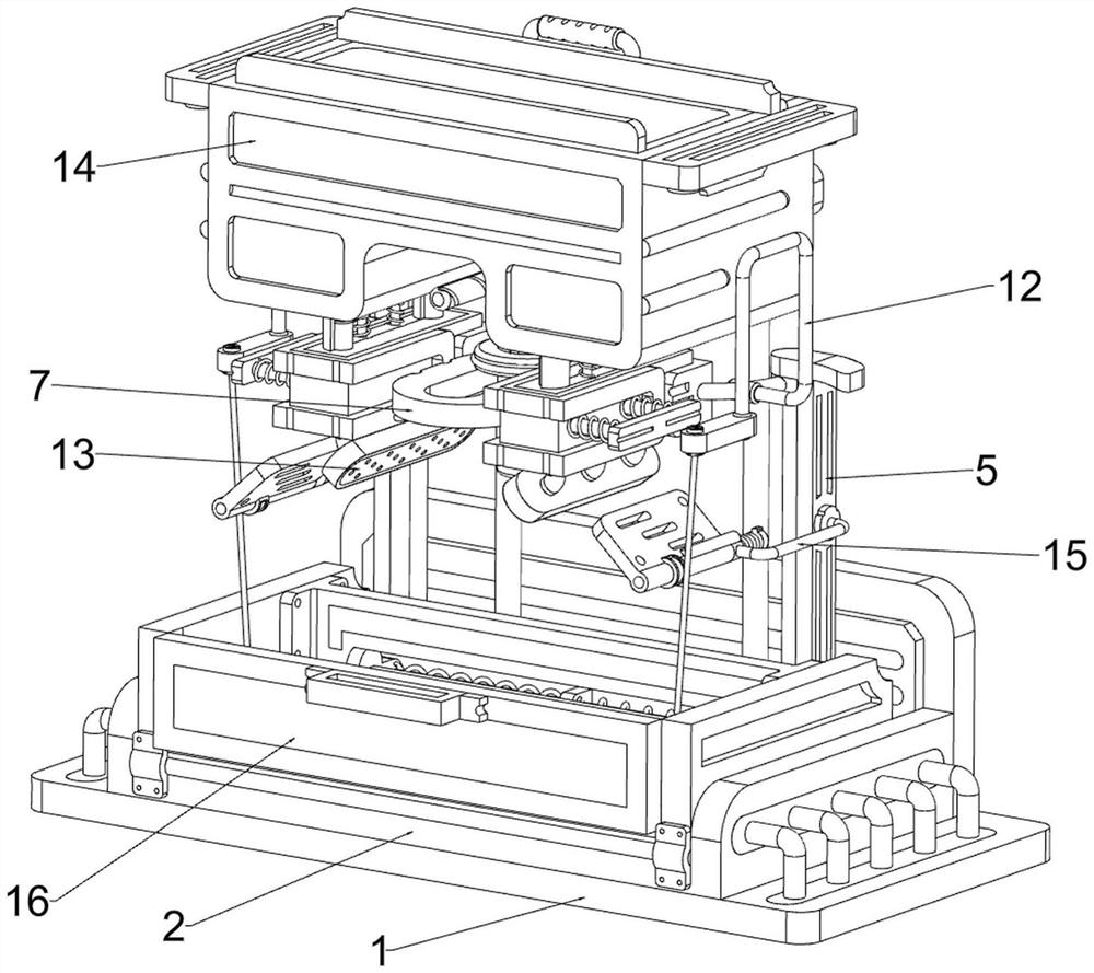
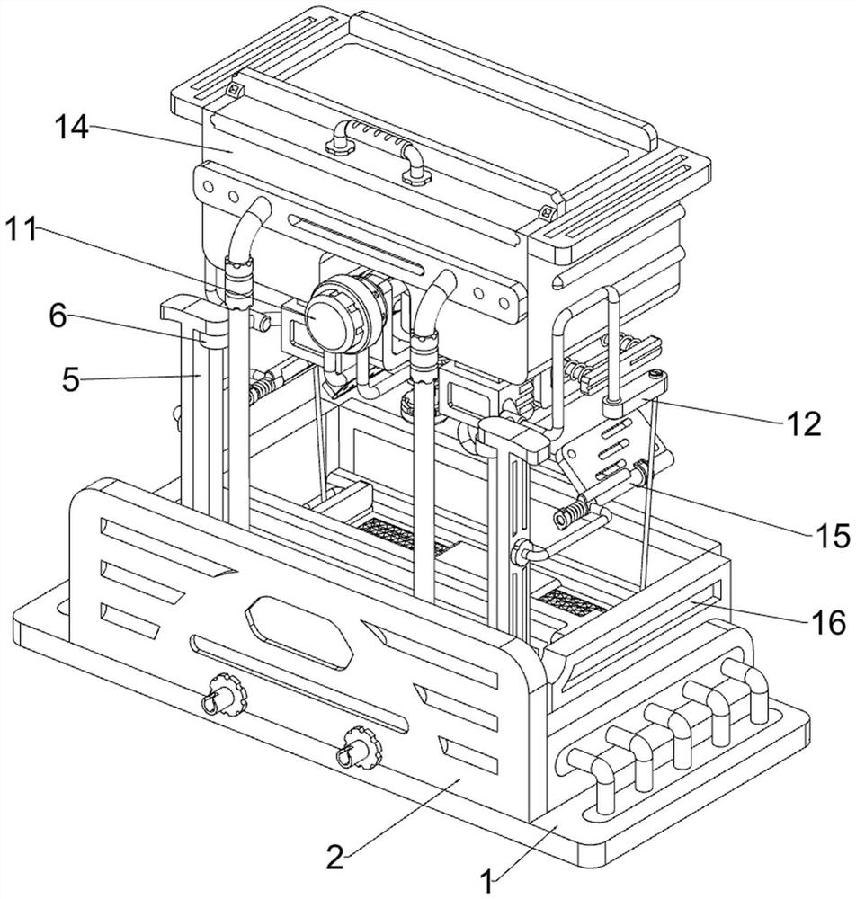
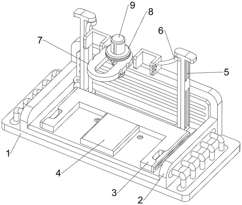
[0039] A micro-grinding device for mechanical manufacturing design, in Figure 1-4 As shown in the figure, it includes a base 1, a support base 2, a connecting base 3, a workbench 4, an electric slide rail 5, a slider 6, a lifting frame 7, a limit block 8, a motor 9, a grinding block 10, an adjustment mechanism 11 and Clamping mechanism 12, the top of the base 1 is provided with a support seat 2, the support seat 2 is provided with a connecting seat 3, the middle of the support seat 2 is welded with a worktable 4 for placing mechanical parts, and the left and right sides of the inner rear of the support seat 2 are The electric slide rails 5 are installed, the upper sides of the two electric slide rails 5 are slidably provided with a sliding block 6, a lifting frame 7 is connected between the two sliding blocks 6, and the lifting frame 7 is slidably provided with a limit block 8 to limit the sliding block 8. A motor 9 for driving is installed on the position block 8, and a grin...

Embodiment 2

[0044] On the basis of Example 1, in figure 1 , Figure 8 , Figure 9 and Figure 10 It also includes a cooling mechanism 13, and the cooling mechanism 13 includes a housing 131, a spray head 132, a connecting pipe 133, a second fixing frame 134, a blocking frame 135, a telescopic spring 136, a push frame 137 and an extension spring 138, The front sides of the two sliders 6 are connected with housings 131 for storing cooling liquid by means of bolts. The bottoms of the two housings 131 are provided with spray heads 132 capable of spraying the cooling liquid, and the tops of the two housings 131 are provided with The connecting pipes 133 for transmitting the cooling liquid are symmetrically arranged in the front and rear. The four connecting pipes 133 are all communicated with the casing 131 on the same side. A second fixing frame 134 is welded to each of the two second fixing frames 134 , and a baffle frame 135 capable of blocking the feeding chute is slidably provided on t...


PUM


Abstract

The invention relates to a grinding device, in particular to a miniature grinding device for mechanical manufacturing design. According to the micro grinding device for mechanical manufacturing and design, clamping work of mechanical parts can be automatically completed, and then it is guaranteed that grinding work is conducted orderly. A miniature grinding device for mechanical manufacturing design comprises a base, a supporting seat, a connecting seat, a workbench, electric sliding rails and the like, the supporting seat is arranged at the top of the base, the connecting seat is arranged in the supporting seat, the workbench is arranged in the middle in the supporting seat, and the electric sliding rails are arranged on the left side and the right side of the rear portion in the supporting seat. When the mechanical part is polished, the polishing block and the sliding block gradually move downwards, the pull rope is loosened, the sliding frame moves inwards under the action of the return spring to clamp the mechanical part, the polishing block makes contact with the mechanical part to conduct polishing work, in this way, clamping of the mechanical part is completed without manual operation, and errors caused by manual operation can be avoided.

Description

technical field [0001] The invention relates to a grinding device, in particular to a micro-grinding device for mechanical manufacturing design. Background technique [0002] The surface or inner hole of mechanically manufactured parts usually requires a certain degree of finish, or the surface has dust, bumps, etc., as well as grinding, cutting or paint layer removal to improve the accuracy of its assembly, usually using a grinding device for grinding. [0003] The publication number is CN213702885U of a micro-grinding device for mechanical manufacturing design, including a working groove, a screw drive mechanism is arranged inside the working groove, the screw drive mechanism is connected with a movable seat, and the upper end of the movable seat is provided with a clamping component, which can move Both sides of the lower end of the seat are fixedly connected with a chip cleaning brush. The back of the chip cleaning brush is provided with a hole that matches with the scre...

Claims


Application Information

Patent Timeline
IPC IPC(8): B24B19/00B24B41/06B24B47/00B24B47/20B24B47/22B24B55/03
CPCB24B19/00B24B41/06B24B47/00B24B47/22B24B55/03B24B47/20Y02P70/10
Inventor 周小青顾锋许进陈惊雷陈广健
Owner NANTONG VOCATIONAL COLLEGE
Why Eureka
Try Eureka