Supercharge Your Innovation With Domain-Expert AI Agents!

Bypass circuit

A bypass circuit and isolation drive circuit technology, applied in electrical components, output power conversion devices, etc., can solve the problems of power module output waveform oscillation, increasing power module volume, and reducing system efficiency.

Pending Publication Date: 2017-06-13
TBEA SUNOASIS
View PDF5 Cites 0 Cited by
  • Summary
  • Abstract
  • Description
  • Claims
  • Application Information

AI Technical Summary

Problems solved by technology

However, when the value of the capacitor C increases, the loss consumed on the resistor R increases, which reduces the efficiency of the system; when the value of the inductor L increases, the volume of the power module increases
In addition, the introduction of LC will cause the output waveform of the power module to oscillate, and will form a voltage spike between the cathode and anode of the thyristor. Therefore, the above bypass scheme puts forward higher requirements on the withstand voltage capability of the thyristor.

Method used


Image

  • Bypass circuit
  • Bypass circuit
  • Bypass circuit

Examples


Embodiment Construction

[0026] In order to enable those skilled in the art to better understand the technical solutions of the present invention, the present invention will be further described in detail below in conjunction with the accompanying drawings and embodiments.

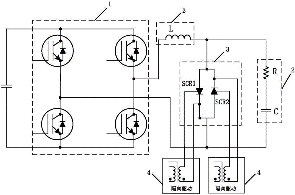
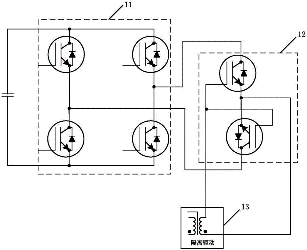
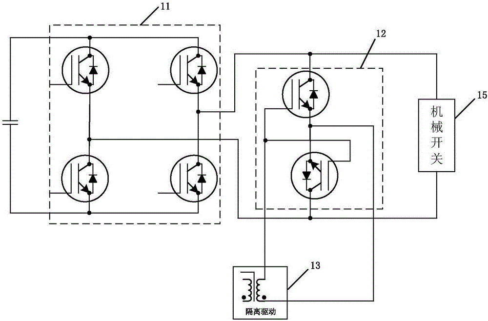
[0027] An embodiment of the present invention provides a bypass circuit, which is connected in parallel on the AC output side of each cascaded module (such as a power module), and the bypass circuit includes a group of full-control switch tubes, which are configured with a drive circuit, To drive each fully-controlled switching tube to be turned on and off. It can be understood that the group of full-control switch tubes is connected in parallel on the AC output side of the cascade module.

[0028] When the cascade module is working normally, the driving circuit controls the driving voltage of each fully-controlled switch tube to be at a negative level, so that each fully-controlled switch tube remains in the off state, and will n...


PUM


Abstract

The invention provides a bypass circuit, which is connected in parallel at the alternating current output side of each cascade connection module; the bypass circuit comprises a group of full control type switching tubes, and is provided with a driving circuit. The bypass circuit has the advantages that the work is reliable; the bypass switching is fast; the size is small; the power consumption is low.

Description

technical field [0001] The invention relates to the technical field of power module cascading, in particular to a bypass circuit. Background technique [0002] In the application where the modules are cascaded to output AC high voltage, in order to ensure the normal operation of the system, the cascaded modules (also called inverter bridges) are generally connected in parallel with bypass circuits. When a module fails, the bypass circuit is used to bypass the faulty module to ensure that other power modules continue to work normally, so that the system operation will not be affected. [0003] Existing bypass circuits for cascaded modules mainly use thyristors or mechanical switches (contactors or relays) to achieve bypass. Such as figure 1 As shown, the bypass circuit adopts the thyristor anti-parallel method. Specifically, the bypass circuit is composed of an AC filter circuit 2 and a thyristor circuit 3 . Wherein the AC filter circuit 2 includes an AC filter inductor L...

Claims


Application Information

Patent Timeline
IPC IPC(8): H02M1/32
CPCH02M1/32H02M1/325
Inventor 吴霆霆李直郝翔李东松王立
Owner TBEA SUNOASIS
Features
  • R&D
  • Intellectual Property
  • Life Sciences
  • Materials
  • Tech Scout
  • Unparalleled Data Quality
  • Higher Quality Content
  • 60% Fewer Hallucinations
Learn More