
Intelligent light control system

An intelligent and control chip technology, applied in the field of light control systems, can solve problems such as poor working stability, and achieve the effects of preventing high voltage damage, improving stability, and improving stability and practicability

Active Publication Date: 2017-06-13
成都零一智慧科技有限公司
View PDF13 Cites 0 Cited by
  • Summary
  • Abstract
  • Description
  • Claims
  • Application Information

AI Technical Summary

Problems solved by technology

[0004] The purpose of the present invention is to overcome the defect of poor working stability of the existing light control system in actual operation, and to provide an intelligent light control system

Method used


Image

  • Intelligent light control system

Examples


Embodiment

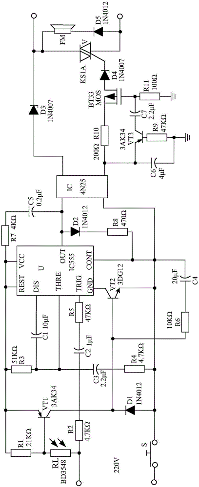
[0017] Such as figure 1 As shown, the present invention mainly consists of the control chip U of model IC55, the photoelectric coupler IC of model 4N25, the bidirectional thyristor V of KS1A, the buzzer FM, the switch S, the diode D5 of model 1N4012, and the model of 1N4007 Zener diode D3, photosensitive control circuit, voltage regulation circuit, and current protection circuit.

[0018] When connected, the P pole of the Zener diode D3 is connected to the first output terminal of the photocoupler IC, and the N pole is connected to the first anode of the bidirectional thyristor V. The P pole of the diode D5 is connected to the second anode of the bidirectional thyristor V, and the N pole is connected to the N pole of the Zener diode D3 after passing through the buzzer. The photosensitive control circuit is respectively connected with the TRIG pin and the DIS pin, as well as the VCC pin and the OUT pin of the control chip U. The voltage regulating circuit is respectively conn...


PUM


Abstract

The invention discloses an intelligent light control system, which is characterized by mainly consisting of a control chip U, a photoelectric coupler IC, a bidirectional thyristor V, a buzzer FM, a switch S, a voltage stabilizing diode D3, a photosensitive control circuit, a voltage regulation circuit, a current protection circuit and the like, wherein the current protection circuit is connected in series between the second output end of the photoelectric coupler IC and a control electrode of the bidirectional thyristor V. A photosensitive control circuit can control the on-off state of a circuit according to the use environment brightness of an illuminating lamp; the voltage output by the photosensitive control circuit is regulated by the control chip U and the voltage regulation circuit, and then outputs stable reference voltage; meanwhile, the photoelectric coupler IC and the bidirectional thyristor V are used for performing double control on the output voltage, so that the stability and the practicability of the intelligent light control system are improved; the energy saving effect of the illuminating lamp is effectively improved.

Description

technical field [0001] The invention relates to a light control system, in particular to an intelligent light control system. Background technique [0002] "Light control system" is favored by people because it can control the opening and closing of electronic products according to the brightness of the environment in which electronic products are used, and can well meet people's requirements for energy saving of electronic products. "Light control system" is also widely used in the control of lighting lamps, so that the lighting lamps can meet people's requirements for energy saving when they are in use. [0003] However, the working stability of the existing light control system is poor in actual operation, resulting in unstable opening and closing of the lighting when in use, resulting in the situation that the lighting is turned on or off by mistake, which seriously affects people's lives. . Contents of the invention [0004] The object of the present invention is to...

Claims


Application Information

Patent Timeline
IPC IPC(8): H05B37/02
CPCH05B47/11H05B47/10Y02B20/40
Inventor 向勇王唯王健翔
Owner 成都零一智慧科技有限公司
Learn More