Bypass device

A bypass device and mounting hole technology, used in transportation and packaging, elevators, elevators in buildings, etc., can solve the problems of affecting the life of the device, weak reliability, limited space, etc., and achieve accurate plugging and unplugging. , to increase the effect of guiding

Active Publication Date: 2017-06-16
SHANGHAI MITSUBISHI ELEVATOR CO LTD
View PDF6 Cites 3 Cited by
  • Summary
  • Abstract
  • Description
  • Claims
  • Application Information

AI Technical Summary

Problems solved by technology

[0005] The space for setting and operating the bypass device in the control panel or the emergency and test operation panel is usually limited. If a bypass device with a simple plug-in method is used, the plug and socket

Method used


Image

  • Bypass device
  • Bypass device
  • Bypass device

Examples


Embodiment 1

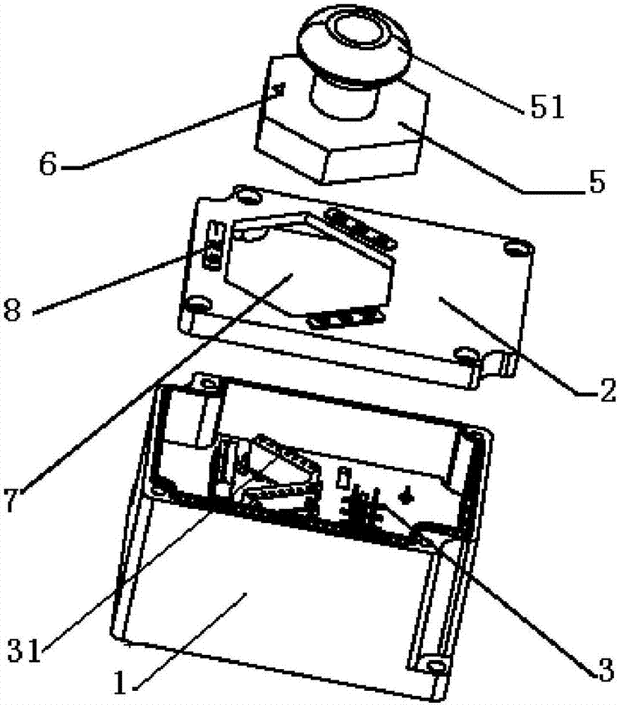
[0062] Such as figure 1 , Figure 4 , Figure 7 As shown, the bypass device includes a box body 1, a front cover 2, and a handle 5;

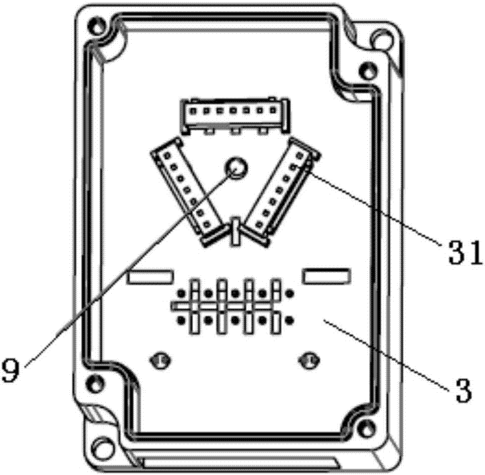
[0063] Such as figure 2 , Figure 5 As shown, the bottom of the box body 1 is fixedly provided with a lower printing plate 3;

[0064] The lower printing plate 3 includes at least one lower insert 31;

[0065] The front cover 2 is buckled and fixed on the box body 1;

[0066] A mounting hole 7 is provided on the front cover 2;

[0067] The top surface of the front cover 2 is provided with one or more position marks 8 at different positions around the installation hole 7;

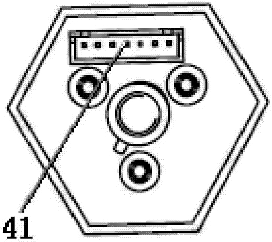
[0068] The circumferential shape of the handle 5 is similar to the shape of the mounting hole 7, and the circumferential dimension of the handle 5 is smaller than the size of the mounting hole 7;

[0069] Such as image 3 , Figure 6 As shown, at least one upper insert 41 is fixed on the bottom surface of the handle 5, and a bypass mark 6 is provided on the top surf...

Embodiment 2

[0078] Based on the bypass device of Embodiment 1, when the upper plug-in 41 on the bottom surface of the handle 5 and the lower plug-in 31 are inserted to the maximum, the top surface of the handle 5 is flush with the top surface of the front cover 2 or is located at the front. In the mounting hole 7 provided on the cover 2.

[0079] In the bypass device of Embodiment 2, when the upper plug-in 41 and the lower plug-in 31 are fully plugged in, the distance from the plug-in position to the front cover 2 should not be too large, because when the plug-ins are combined, the handle 5 is actually the mounting hole 7 of the front cover 2 As a fulcrum, the distance from the insertion position to the front cover 2 is too large, which may easily cause the upper insert 41 to fail to insert the lower insert 31 .

Embodiment 3

[0081] Based on the bypass device in Embodiment 1, when the handle 5 is inserted into the installation hole 7 , the unilateral gap between the handle 5 and the installation hole 7 is between 0.1 mm and 0.5 mm.

[0082] The unilateral gap should not be too small to consider the line tolerance between the printing plate, box body, and upper and lower plug-ins; the unilateral gap should not be too large for the purpose of limiting.


PUM


Abstract

The invention discloses a bypass device which comprises a box body, a front cover and a handle. A lower-portion printing plate at the bottom of the box body comprises at least one lower-portion plug part, the front cover is buckled and fixed to the box body, the front cover is provided with an installing hole, and the top surface of the front cover is provided with position signs. The handle is similar to the installing hole in peripheral shape. At least one upper-portion plug part is fixed to the bottom surface of the handle, and a bypass sign is arranged on the top surface. When the handle is embedded into the installing hole and the bypass sign corresponds to the different position signs, the upper-portion plug parts on the bottom surface of the handle are oppositely plugged with the lower-portion plug parts of the lower-portion printing plate, and different external route communicating states are formed through different opposite-plugging combinations of the upper-portion plug parts and the lower-portion plug parts. The bypass device is convenient to use, and the plug parts are accurate in opposite plugging and positioning.

Description

technical field [0001] The invention relates to a bypass device for an electrical circuit, and the bypass device for bypassing a landing door lock circuit and a car door lock circuit. Background technique [0002] In electrical circuit design, switching between circuits is usually achieved through bypass devices. [0003] Take the elevator field as an example: In order to detect the opening and closing of elevator landing doors and car doors, a door lock switch is set on each floor door and car door and connected in series to form a door lock circuit. When any door is opened, the door lock circuit is disconnected, causing the elevator to stop running. The inability of the elevator to run due to damage to the door lock contacts may cause trapped people to fail, and it will also cause difficulties for professionals to overhaul and maintain. [0004] In December 2014, the General Administration of Quality Supervision, Inspection and Quarantine of the People's Republic of Chin...

Claims


Application Information

Patent Timeline
IPC IPC(8): B66B5/02B66B13/14
CPCB66B5/0087B66B5/02B66B13/14
Inventor 何成管敏强张皓然
Owner SHANGHAI MITSUBISHI ELEVATOR CO LTD
Why Eureka
Try Eureka