Electric-motor-driven liquid pump

一种流体泵、电动机的技术,应用在电动组件、径向流动泵、机器/发动机等方向,能够解决限制等问题,达到容易输送的效果

Active Publication Date: 2017-06-16
FTE AUTOMOTIVE GMBH & CO KG
View PDF9 Cites 16 Cited by
  • Summary
  • Abstract
  • Description
  • Claims
  • Application Information

AI Technical Summary

Problems solved by technology

Moreover, in this structure, there is a non-negligible axial installation space requirement, which limits the possibility of using such pumps

Method used


Image

  • Electric-motor-driven liquid pump
  • Electric-motor-driven liquid pump
  • Electric-motor-driven liquid pump

Examples


Embodiment Construction

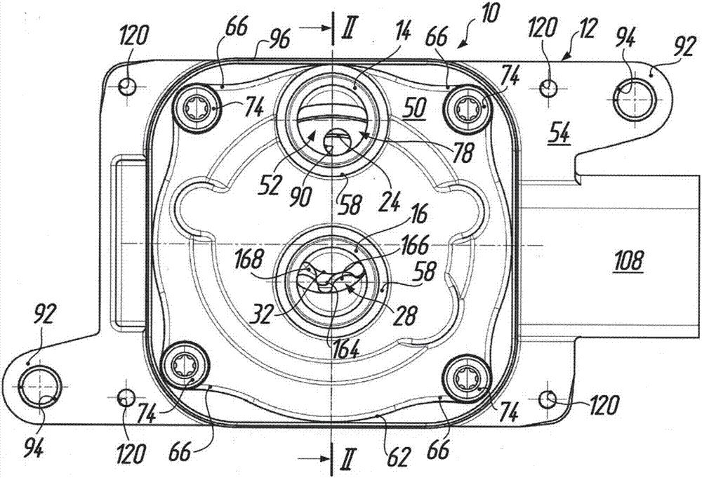
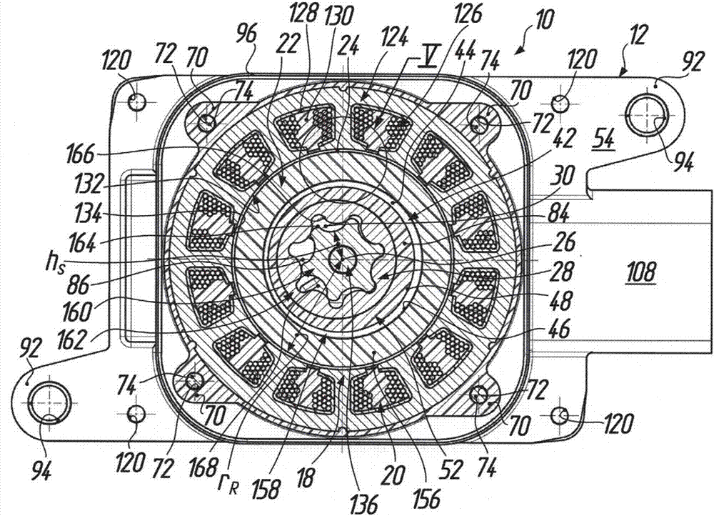
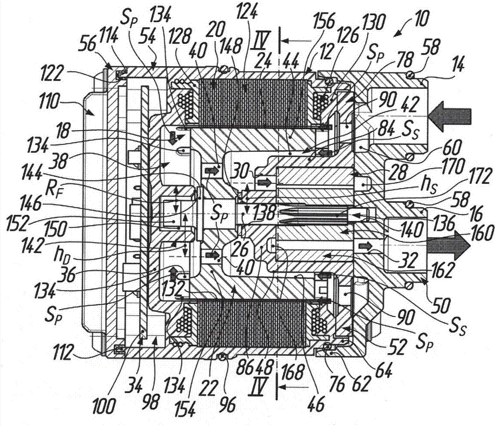
[0035] In the figures, reference numeral 10 generally designates an electric motor-driven fluid pump usable in or at a transmission of a motor vehicle, in particular as an oil pump for cooling and / or lubrication. The fluid pump 10 includes a housing generally designated by reference numeral 12 having a suction connection 14 and a pressure connection 16 . Specifically, as figure 2 As shown, an electric motor 18 is disposed within a housing 12 and includes a stator 20 and an inner rotor 22 located at the housing. A rotor 22 is accommodated within the stator 20 with an annular gap 24 therebetween and is driven in rotation about an axis of rotation 26 . exist figure 2 with Figure 4 28, the delivery device is generally designated by reference numeral 28, said delivery device 28 has a suction port 30 fluidly connected to the suction connection 14 of the housing 12 and a pressure outlet 32 ​​fluidly connected to the pressure connection 16 of the housing 12, The conveying devic...


PUM


Abstract

A liquid pump (10) includes a housing (12), an electric motor (18), a conveying device (28), and an electronic power unit (34). The housing has a suction connection (14) and a pressure connection (16). A stator (20) and a rotor (22) are provided in the electric motor, and the conveying device (28) rotationally driven by the rotor has a suction inlet (30) and pressure outlet (32) which communicate with the suction connection and the pressure connection respectively. The electronic power unit (34) is for the electric motor located on the rear side of a partition wall (36) of the housing, the partition wall being adjacent to the rotor and extending transversely to the axis (26) of rotation of the rotor. For a compact structure and optimized cooling, the suction inlet is arranged at a height (hS) from the axis of rotation smaller than an inner radius (rR) of an annular gap (24) between the stator and rotor, whereas the rotor (22) has a passage (40) extending preferably at a constant height (hD) from the axis of rotation, so that a liquid inducted by way of the suction connection (14) is constrainedly guided in part via the annular gap (24) and undergoes a deflection at the partition wall, while cooling the latter before passing through the passage of the rotor to the suction inlet.

Description

technical field [0001] The invention relates to an electric motor driven fluid pump according to the preamble of claim 1 . In particular, the present invention relates to fluid pumps (mainly made of plastic parts these days) used on a large scale in the automotive industry, such as lubricating oil pumps, cooling oil pumps, auxiliary oil pumps or actuator pumps, due to the low weight of the fluid pumps of the present invention And power drive control can be performed according to needs, and the fluid pump of the present invention helps to reduce fuel consumption and carbon dioxide emission. [0002] technical background [0003] It is known that low pollutant emissions and the lowest possible fuel consumption of motor vehicles during operation play an important role in the development of new vehicles and vehicle concepts; also due to legal regulations, these aspects will become more of a focus for developers in the future . With this purpose in mind, adjustable electric oil ...

Claims


Application Information

Patent Timeline
Patent Type & Authority Applications(China)
IPC IPC(8): F04C11/00F04C2/10
CPCF04C2/10F04C11/008F04C2/102F04C15/0096H02K9/19F04C15/008F04C2240/30F04C2240/40F04C2210/20F05B2210/11F04B17/03F04B53/08F04D13/0653F04D29/5813F04D29/5806F04D1/04F04D13/06F04D29/586
Inventor A·鲁尔M·迪拉夫
Owner FTE AUTOMOTIVE GMBH & CO KG
Why Eureka
Try Eureka