
Spatial multimode arrayed cantilever beam piezoelectric energy collecting device

A piezoelectric energy collection device technology, applied in the direction of piezoelectric effect/electrostrictive or magnetostrictive motors, electrical components, generators/motors, etc., can solve the problem of narrow working frequency band and achieve high energy density collection , High energy harvesting efficiency and compact structure

Active Publication Date: 2017-06-16
HEFEI UNIV OF TECH
View PDF6 Cites 29 Cited by
  • Summary
  • Abstract
  • Description
  • Claims
  • Application Information

AI Technical Summary

Problems solved by technology

[0009] The purpose of the present invention is to improve the defect that common cantilever beam piezoelectric energy harvesting devices have a narrow operating frequency band and can only collect vibrations in a single direction, and provide a space multi-mode array cantilever piezoelectric energy harvesting device. The cantilever beam piezoelectric energy harvesting device has the advantages of high space utilization, compact structure, high collection energy density, multi-directional vibration collection, and wide operating frequency band.

Method used


Image

  • Spatial multimode arrayed cantilever beam piezoelectric energy collecting device
  • Spatial multimode arrayed cantilever beam piezoelectric energy collecting device

Examples


specific Embodiment approach

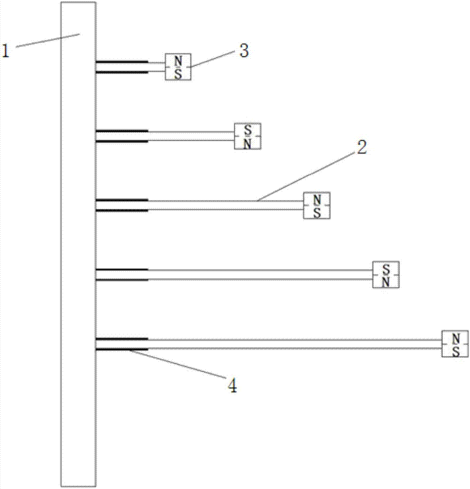
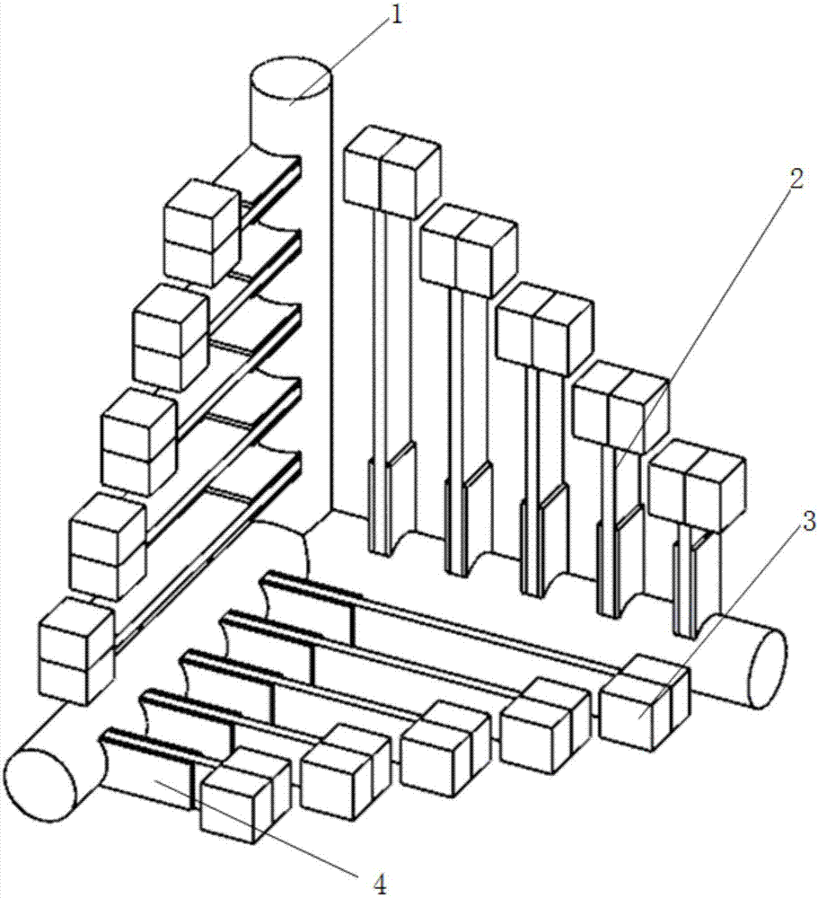
[0034] A space multi-mode array cantilever beam piezoelectric energy harvesting device, including a basic frame, a cantilever beam array, a magnet block, and a piezoelectric power generation sheet. The basic frame 1 is composed of three metal tubes that are perpendicular to each other. It is composed of multiple cantilever beams 2 and arranged in sequence from short to long. A set of cantilever beam arrays is arranged on each metal tube of the foundation frame 1, and the cantilever beam array is perpendicular to the metal tube where it is located. The installation of the cantilever beam array The direction should ensure that its vibration direction is parallel to the length direction of the metal pipe where it is located. A magnet block 3 is installed at the end of each cantilever beam 2 in the cantilever beam array, and the same magnetic poles of the magnet blocks 3 between adjacent cantilever beams 2 are opposite. The roots of the cantilever beams 2 are all pasted with piezoe...


PUM


Abstract

The invention discloses a spatial multimode arrayed cantilever beam piezoelectric energy collecting device, which comprises a base skeleton, a cantilever beam array, magnets and piezoelectric power generation pieces, wherein the base skeleton is composed of metal tubes distributed in a spatial coordinate mode; the cantilever beam array is composed of multiple cantilever beams which are arranged sequentially from short to long; each metal tube of the base skeleton is provided with a group of cantilever beam array; the cantilever beam array is vertical to the metal tube; the mounting direction of the cantilever beam array needs to ensure the vibration direction to be parallel with the length direction of the metal tube; the tail end of each cantilever beam in the cantilever beam array is provided with the magnet; the same magnetic poles of the magnets between adjacent cantilever beams are opposite; and the piezoelectric power generation piece is adhesive to the root of each cantilever beam. The working frequency domain of the structure is wide, the structure is compact, the space utilization rate is high, the power generation efficiency is high, and the energy utilization efficiency can be improved and self power supply of a low power consumption device can be realized through collection of external vibration energy.

Description

[0001] Technical field: [0002] The invention relates to the field of energy recovery, belongs to vibration piezoelectric energy conversion technology, and mainly relates to a space multi-mode array cantilever beam piezoelectric energy collection device. [0003] Background technique: [0004] The application of wireless systems has penetrated into every corner of the world, such as wireless networks based on IEEE802.11 standards and portable electronic devices based on Bluetooth standards, which have been widely used in daily life. Compared with the traditional wired system, the wireless system has many advantages, such as easy to use, flexible operation, and can be configured at will. As an important application of the wireless system, a technology called Wireless Sensor Network (WSN) has developed rapidly. This technology is to place tiny wireless sensor nodes in machines or building structures to monitor their operating status in real time. The demand for power supply eq...

Claims


Application Information

Patent Timeline
Patent Type & Authority Applications(China)
IPC IPC(8): H02N2/18
CPCH02N2/188
Inventor 邓华夏杜宇王哲敏张进于连栋马孟超
Owner HEFEI UNIV OF TECH
Learn More