A fully automatic low temperature vacuum frying device

A technology of low-temperature vacuum frying and vacuum frying tanks, which is applied in oil/fat baking, loading/unloading of ovens, food ovens, etc. General manual operation and other problems to achieve the effect of preventing offset, reducing manual operation and increasing sealing

Active Publication Date: 2019-09-06
吕丙生
View PDF8 Cites 0 Cited by
  • Summary
  • Abstract
  • Description
  • Claims
  • Application Information

AI Technical Summary

Problems solved by technology

However, with long-term use and observation, the above-mentioned all-in-one frying and deoiling machine still has shortcomings: when placing the material frame, it is generally operated manually, and it is directly placed on the rotating device of the vacuum frying tank
This is easy to place the deviation, and when the heating tube in the vacuum frying tank is on the side, it is easy to crush the heating tube when the material frame is placed. At the same time, during the high-speed deoiling in the later stage, the deviation of the material frame will easily lead to center instability. being thrown out, causing equipment failure
When frying, the material frame cover of the material frame is usually directly covered on the material frame, and it is easy to be thrown out during high-speed deoiling in the later stage, causing food to overflow and causing equipment failure
Furthermore, the existing vacuum frying device cannot change the frying environment in the vacuum tank according to the requirements of different foods, so that the crispness of the fried food cannot be optimal. The present invention studies on the basis of this problem. with improved

Method used


Image

  • A fully automatic low temperature vacuum frying device
  • A fully automatic low temperature vacuum frying device
  • A fully automatic low temperature vacuum frying device

Examples


Embodiment Construction

[0021] The invention will be further described in conjunction with the accompanying drawings and specific embodiments.

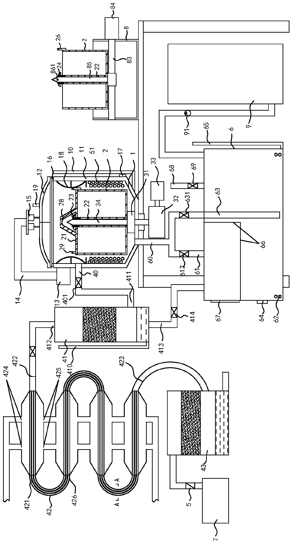
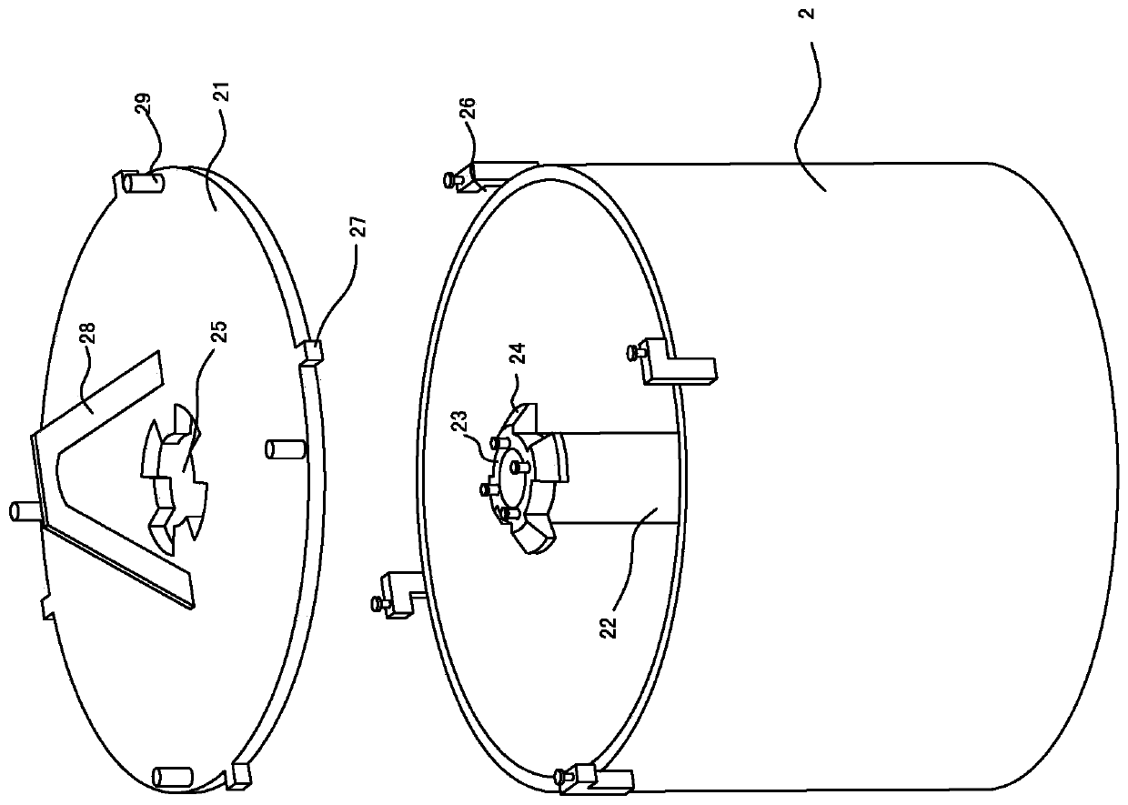
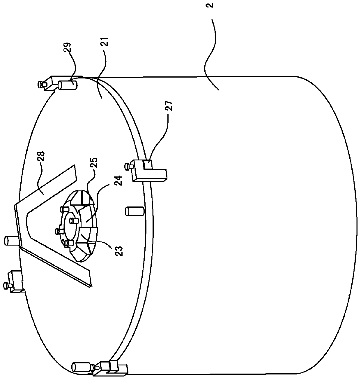
[0022] refer to Figure 1 to Figure 4 , the present embodiment provides a full-automatic low-temperature vacuum frying device, including a vacuum frying tank 1 arranged on a frame in turn, a discharge device 8 located on one side of the vacuum frying tank 1, a heating device, and a vacuum frying tank. The tank 1 is connected to a cooling device through a vacuum tube 40. The vacuum tube 40 is provided with a vacuum breaking valve 401. The vacuum frying tank 1 includes a tank body 11, a tank cover 12 arranged on the top of the tank body 11, and a tank cover 12. The vacuum sensor 19 used to detect the vacuum state inside the tank body 11 and the first liquid level gauge 10 arranged on one side of the tank body 11 and used to measure the oil level inside the tank body 11, the upper end of the tank body 11 is provided on the outside First motor 13, first motor 1...


PUM


Abstract

The invention relates to the technical field of food processing, in particular to a full automatic low-temperature vacuum frying device. The device comprises a vacuum frying tank, a discharging device, a heating device and a cooling device which are arranged on a rack in sequence, the discharging device is arranged at one side of the vacuum frying tank, the cooling device is communicated with the vacuum drying tank through a vacuum tube, the vacuum frying tank comprises a tank body and a tank lid arranged on the upper portion of the tank body, a rotating disc is arranged in the center of the bottom inside the tank body, the rotating dick is driven by a rotating motor to rotate, a guiding shaft is arranged on the rotating disc, a material frame is arranged on the rotating disc and provided with a shaft sleeve allowing the material frame to be inserted into the guiding shaft, a material frame lid is arranged on the material frame, a mounting block is arranged at the upper end of the shaft sleeve of the material frame, protruding blocks are arranged on the mounting block, the material frame lid is provided with a through hole matched with the mounting block, the material frame lid is located below the mounting block when covering the material frame, clamping grooves are upwards formed in the outer side around the upper end of the material frame, and the material frame lid is provide with clamping blocks matched with the clamping grooves.

Description

technical field [0001] The invention relates to the technical field of food processing, in particular to a fully automatic low-temperature vacuum frying device. Background technique [0002] Vacuum low-temperature frying (VF for short) refers to putting food in a negative pressure state in a vacuum state, using vegetable oil with strong antioxidant capacity as a heat transfer medium, and the water in the intercellular space of fruits and vegetables will rapidly vaporize and expand, which is the result of loose tissue formation. porous structure. Vacuum frying technology organically combines frying and dehydration. Food processing under relatively anoxic conditions can reduce or even avoid the harm caused by oxidation, and at the same time, it can well preserve the fragrance of the raw materials themselves; Moreover, during the vacuum frying process, the oil is in a state of negative pressure, and the gas dissolved in the oil escapes in large quantities quickly, and the wate...

Claims


Application Information

Patent Timeline
Patent Type & Authority Patents(China)
IPC IPC(8): A21B5/08A21B3/07A21B3/00
Inventor 吕丙生
Owner 吕丙生
Why Eureka
Try Eureka